Download
1 / 16
160 likes | 291 Views
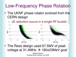
m. Lower-Frequency RF Phase Rotation Techniques for Both Muon Signs. Low-Frequency Phase Rotation. The UKNF phase rotator evolved from the CERN design D E reduction occurs in a single RF bucket: Rees design uses 31.4MHz RF to achieve 180±23MeV intended for a cooling ring.

E N D
m Lower-Frequency RF Phase Rotation Techniques for Both Muon Signs Stephen Brooks NuFact’06, UC-Irvine, August 2006
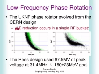
Low-Frequency Phase Rotation • The UKNF phase rotator evolved from the CERN design • DE reduction occurs in a single RF bucket: • Rees design uses 31.4MHz RF to achieve 180±23MeV intended for a cooling ring Stephen Brooks NuFact’06, UC-Irvine, August 2006
Problem with Two Signs • Negative muons are rotated backwards Stephen Brooks NuFact’06, UC-Irvine, August 2006
Stephen Brooks NuFact’06, UC-Irvine, August 2006
Single-Sign Rotator • Negative muons are rotated backwards Stephen Brooks NuFact’06, UC-Irvine, August 2006
Solution (idea) for Two Signs I. Mixed-sign drifted bunch from decay channel II. Separate signs with on-peak RF III. Drift further to get separation in time IV. Put bunches on opposite sides of two adjacent wave troughs, to get the reverse sign separation and remaining phase rotation simultaneously Stephen Brooks NuFact’06, UC-Irvine, August 2006
Does Dual-Sign Idea Work? • Initial concept worked moderately well • Some optimisation gave this solution for 31.4MHz Stephen Brooks NuFact’06, UC-Irvine, August 2006
Stephen Brooks NuFact’06, UC-Irvine, August 2006
Dual-Sign Rotator • Less of each sign, but more in total Stephen Brooks NuFact’06, UC-Irvine, August 2006
Multi-Harmonic System • Idea: allowing variation of RF frequencies in the optimisation could produce higher yields by better shaped rotation • Allowed harmonics h=n/6 from 1/6 to 4 times the 31.4MHz fundamental • Re-synchronisation every 6 periods (191ns) • Optimisation produced this solution; not yet clear if this can be improved further Stephen Brooks NuFact’06, UC-Irvine, August 2006
Stephen Brooks NuFact’06, UC-Irvine, August 2006
Multi-Harmonic Rotator • Better in most regards, produces more b’s Stephen Brooks NuFact’06, UC-Irvine, August 2006
FS2a Neuffer Rotator • Attempted comparison Stephen Brooks NuFact’06, UC-Irvine, August 2006
FS2a Bunch Population 30 b 58 b Stephen Brooks NuFact’06, UC-Irvine, August 2006
Alternative Calculation 80 MeV c.f. 46 MeV 2 ns c.f. 11 ns 0.16 eV.s (rectangular) per b 4.8 eV.s for 30 b, 9.3 eV.s for 58 b Stephen Brooks NuFact’06, UC-Irvine, August 2006
Conclusion • The main differences between LF schemes and the Neuffer buncher are: • LF schemes use less ‘voltage’ (~3x) • Bunch train length is much less (~4x) • Resultant total eL is somewhat less (~½) • Though each individual bunch is longer • But so far: • Efficiency is not quite as good (-10%) • LF channels are slightly longer (+35%) Decay Ring? Stephen Brooks NuFact’06, UC-Irvine, August 2006