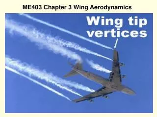
ROTARY WING AERODYNAMICS
630 likes | 1.3k Views
ROTARY WING AERODYNAMICS. CW3 Tom Benzenberg UH-60 IPC/MOI CLASS 00-04. REFERENCES. FM 1-203, Fundamentals of flight Student Handout - Fundamentals of fixed and rotary wing aerodynamics Student Handout - Applied Aerodynamics TC 1-212, Aircrew Training Manual

ROTARY WING AERODYNAMICS
E N D
Presentation Transcript
ROTARY WING AERODYNAMICS CW3 Tom Benzenberg UH-60 IPC/MOI CLASS 00-04
REFERENCES • FM 1-203, Fundamentals of flight • Student Handout - Fundamentals of fixed and rotary wing aerodynamics • Student Handout - Applied Aerodynamics • TC 1-212, Aircrew Training Manual • UH-60 IPC Daily Class Lesson Plan Outline
Learning Objectives • Applied and simplified understanding of helicopter aerodynamic characteristics • Correlate relationships between these characteristics • Demonstrate ability to teach in a classroom environment during IPC
Rotary Wing Aerodynamic Subject Areas • Aerodynamic factors • Relative wind • Induced flow • Resultant Relative wind • Angle of incidence/Angle of Attack • Lift and Drag Formula • Total Aeordynamic force • Induced Flow production • Airflow During a hover
Rotary Wing Aerodynamics Subject Areas (Cont) • Translating tendency • Hovering attitude • Mechanical and pilot inputs • Dissymetry of lift • Blade Flapping • Blade lead and lag • Retreating Blade Stall
Rotary Wing Aerodynamic Subject Areas (Cont) • Compressibility • Settling with power • Off set hinges • Dynamic Rollover
Total Aerodynamic force • Resultant of lift and drag • Extends from center of pressure • Represents the actual force exerted on the airfoil.
In Ground Effect Hover (IGE) • Ground/Airflow interaction results in less induced flow • Less induced flow means less induced drag • Power required to hover is less
Out of Ground effect Hover (OGE) • Air accelerates downward without interruption with ground • Vorticies are not blown away from system • High induced flow creates high induced drag • Power is greater to overcome drag • Torque is increased however lift produced remains the same
Translating Tendency • Compensated for by the mechanical mixing unit (Collective to Roll) and cyclic feathering. • Amount of feathering (left cyclic) increases as gross weight increases and decreases as weight decreases.
Fuselage hovering attitude • Because of this effect the aircraft will tend to hover left side low. • Aircraft will hover nose high because of lack of lift on stabilator and a CG located slightly aft. This is compensated for in forward flight. • This nose high hover attitude is by design to increase potential load.
Dissymmetry of lift • Blade flapping • Blade lead and lag • Cyclic Feathering • Retreating Blade Stall • Compressibility
Dissymmetry of lift. • Defined as unequal lift between the advancing and retreating halves of the rotor disk. • In forward flight: • Advancing blade, • Relative wind = Forward speed + Rotational speed • Retreating blade, • Relative wind = Forward speed - Rotational speed
Dissymmetry of lift. • For controlled flight, the lift on the two sides of the disk must be equal. • The difference in velocity is compensated for by changes in the angle of attack either by blade flapping or by forward longitudinal cyclic pitch. • This may be done by the pilot or automatically in more advanced aircraft.
Dissymmetry of lift. • As airspeed increases, there is only one section of the retreating blade that is able to produce positive lift. • The entire advancing blade is producing lift.
Dissymmetry of lift. • The retreating blade consists of the following areas: • Reverse flow. The area from the rotor hub to where the forward speed of the helicopter equals the rotational speed of the rotor blade. The blade is actually deflected downward due to the air striking it on the upper chamber.
Dissymmetry of lift. • Negative stall. The rotor speed in this area is fast enough to overcome the forward speed of the helicopter, but the air is striking the blade above the critical angle of attack and on the upper chamber above the chord.
Dissymmetry of lift. • Negative lift. The air is striking this section of the blade at a lower angle of attack, but it is above the chord again, creating a negative lift. This section of the blade is deflected downward.
Dissymmetry of lift. • Positive lift. The air strikes this section of the blade below the chord line and below the critical angle of attack. This is the only area of the retreating blade that is actually producing upward lift. It must create enough lift to overcome the entire advancing blade, as well as the negative lift from the retreating blade.
Dissymmetry of lift. • Positive stall. The air strikes this portion of the blade below the chord line, but above the critical angle of attack. This is the area where Retreating Blade Stall occurs.
Dissymmetry of lift. • What it looks like:
Dissymmetry of lift. • Compensating for dissymmetry of lift: • Blade flapping. The advancing blade flaps up automatically which decreases its angle of attack and reduces the lift on the blade. The retreating blade automatically flaps down from a loss of lift, which increases the angle of attack and increases lift.
Dissymmetry of lift. • Compensating for dissymmetry of lift: • Cyclic feathering. The pilot applies forward cyclic when he feels the nose pitching up from blade flapping. This is the primary means of compensating for dissymmetry of lift.
Dissymmetry of lift. • Another view:
Retreating blade stall. • The retreating blade of a helicopter tends to stall in forward flight in the following conditions: • High gross weight. • Low rotor RPM. • High density altitude. • High “G” maneuvers. • Turbulence.
Retreating blade stall. • Retreating blade stall limits the high-speed potential of a helicopter. As the forward speed of the helicopter increases, the retreating blade loses airspeed while the airspeed of the advancing blade is increasing. To compensate for this difference, the retreating blade must have a higher angle of attack or it would not produce equal lift.
Retreating blade stall. • As airspeed increases, the angle of attack on the retreating blade must also increase. The fastest area of the blade, the tip, will eventually stall.
Compressibility • Subsonic airflow is incompressible (It acts the same as hydraulic fluid) • Transonic and Supersonic flows become compressible • Drag increases & Lift decreases • Vibrations become more severe • Shock wave formation • Center of Pressure varies
Compressibility • Conditions conducive to compressibility • High Airspeed • High rotor RPM • High Gross Weight • High Density altitude • Low temperature • Turbulent air
Compressibility • Corrective action • Slow down the aircraft • Decrease pitch angle (decrease collective) • Minimize G loading • Decrease RPM
Settling with Power • Settling with power occurs when the helicopter settles in its own downwash. • Conditions required for Settling with power are • 300-1000 fpm rate of descent • power applied (> than 20% availble power) • Near zero airspeed (Loss of ETL)
Settling with Power • Increase in induced flow results in reduction of angle of attack and increase in drag • This creates a demand for excessive power and creates greater sink rate • Where the demand for power meets power available the aircraft will no longer sustain flight and will descend.
Settling With Power. • Can occur during: • Downwind approaches. • Formation approaches and takeoffs. • Steep approaches. • NOE flight. • Mask/Unmask operations. • Hover OGE.
Settling With Power. • Symptoms: • A high rate of descent (300 to 500 fpm minimum). • High power consumption (over 20% of power available). • Loss of collective pitch effectiveness. • Vibrations. • Corrective actions: • Establish directional flight. • Lower collective pitch. • Increase RPM if decayed. • Apply right pedal.
Dynamic Rollover • With a rolling moment and a pivot point if the helicopter exceeds a critical angle it will roll over. • Factors that affect the critical angle • Lateral CG • Cross winds • Gross weight • Asymetrical loading • Human error
Summary • Aerodynamic Factors • Lift and Drag • Total Aerodynamic Force • Air Flow during Hovering • Translating Tendency • Dissymmetry of lift