Download
1 / 29
330 likes | 609 Views
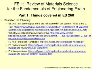
FE-1: Review of Materials Science for the Fundamentals of Engineering Exam. Based on the following: ES 260. But some topics in FE are not covered in our course. Parts 2 and 3.

E N D
FE-1: Review of Materials Sciencefor the Fundamentals of Engineering Exam • Based on the following: • ES 260. But some topics in FE are not covered in our course. Parts 2 and 3. • Text: https://www.wileyplus.com/WileyCDA/Section/Fundamentals-of-Materials-Science-and-Engineering-An-Integrated-Approach-4th-Edition.id-810680.html • Virtual Materials Science & Engineering: http://bcs.wiley.com/he-bcs/Books?action=mininav&bcsId=6957&itemId=1118061608&assetId=278281&resourceId=27445&newwindow=true • FE free Reference Handbook: http://cbt.ncees.org/fe-reference-handbook/ • FE review manual: http://ppi2pass.com/shop/fe-eit-exam/fe-eit-exam-review-materials/fe-review-manual-ferm3.html • Practice problems: http://ppi2pass.com/shop/fe-eit-exam/fe-eit-exam-review-materials/fe-practice-problem-package.html Part 1: Things covered in ES 260 Last revised February 22, 2014 by W.R.Wilcox at Clarkson University.
Bonding in solids • As two atoms approach one another, they at first experience an attraction. • They repel one another when they are brought very close. • r0 is the equilibrium distance. • The type of bonding in a solid depends on the behavior of the atoms' outer “valence” electrons. • Metallic: outer electrons shared in a cloud or sea. • Ionic • Cations have given up one or more electrons • Anions have gained one or more electrons • Covalent: atoms share outer electrons • Mixed ionic and covalent • Van der Waals: electrostatic due to non-uniform charge distribution. Weak
Crystal structure • Pure metals are usually FCC, BCC or HCP. • Except for hexag'l, number/cell:1/8 at corners1/2 at face centersAll of body centered • Coordination number:nearest neighbors • Packing fraction:space occupied by hard sphere atoms. Need a = f(r) • Theoretical density from MW, at/cell, a. • Long-range order. The unit cell is the smallest repeat unit. • There are 14 Bravais lattices, with each point representing the same atom or collection of atoms.
[111] where the overbar represents a negative index => Miller Indices for Crystallographic Directions Algorithm z 1. If necessary, translate the vector so it starts at the origin.2. Read off the end of the vector in increments of unit cell dimensions a, b, and c.3. Adjust these to the smallest integer values.4. Enclose in square brackets without commas. That is, [uvw] y x examples:1, 0, ½ => 2, 0, 1 => [201] -1, 1, 1 families of directions <uvw> , for example: VMSE with examples, problems, exercises
Miller Indices for Crystallographic Planes • Reciprocals of the three axial intercepts for a plane, cleared of fractions & common multiples. • All parallel planes have the same Miller indices. • Algorithm (procedure): 1. If the plane passes through the origin, translate so it does not. 2. Read off the intercepts of the plane with the axes in increments of the lattice constants (a, b, c). For example, 1, 2, 2 3. Take reciprocals of those intercepts. If it is parallel to an axis so that it doesn’t intersect it, the reciprocal is 0. For example, 1, ½, ½ 4. Convert the numbers to the smallest possible integer values.For example, 2, 1, 1 5. Enclose those numbers in parentheses, with no commas.For example (211). 6. As with directions, a bar over a number indicates it is negative. • VMSE with illustrations, problems, exercises • Families of equivalent planes. For a cubic structure, for example:
Hexagonal Close-Packed Structure (HCP) z example a1a2a3 c 1 A sites Top layer 1. Intercepts -1 1 1 1/ 2. Reciprocals -1 1 c 1 0 -1 1 a2 Middle layer B sites 3. Reduction 1 0 -1 1 A sites Bottom layer a3 a 4. Miller-Bravais Indices (1011) a1 ABAB... Stacking Sequence for close-packed planes in HCP Denoting Crystallographic Planes in a Hexagonal Lattice
X-ray diffraction • Bragg's Law when x-rays reflected from parallel atomic planes dhkl apart: nλ = 2dhklsinθ where: • n is a small integer • λ is the wavelength of the x-rays • θ is the between the x-ray beam and the planes • For a cubic structure with lattice constant a and Miller indices h, k, l: • Used for determ'n of: • structure • orientation • identity
Point defects • Pure materials: • Interstitials (atoms between normal lattice sites) • Vacancies (empty lattice sites). Concentration increases as T is increased. • Impurities: • Substitutional sites • Interstitial sites (when much impurity atom much smaller than host) • Diffusion of impurity A from high concentration C to low concentration:Fick's first law: J = - D (dC/dx) • where C can be in units of kg A/m3 or mol A/m3 • D is the diffusion coefficient in units of m2/s • J is the diffusion flux in kg A/m2.s or mol A/m2.s. • For solids, D increases rapidly as T is increased according to:D = D0 exp(-Q/RT) where • D0 is the pre-exponential constant (maximum value D can have at high T). • Q is the activation energy for diffusion (e.g. in J/mol, eV/atom) • R is 8.314 J/mol.K if Q in J/mol.
Mechanical Properties Tensile test • When tension is applied to a rod, the rod becomes longer: • where l0is the initial length and l is the length when stress is applied. • The engineering strain is defined as the relative change in length, i.e.: l0 l Engineering stress: = F/A0 Before stressed After stressed When the stress is removed and the strain returns to 0, this reversible deformation is called "elastic." Stretching of bonds only. Images such as this are from the FE Manual that you will use during the exam.
True stress and strain Images such as these are from the FE Manual that you will use during the exam.
Plastic Deformation • P is the "proportional limit" above which the stress-strain behavior is no longer linear. • As stress is increased, eventually it is so large that when it is removed, some deformation remains. That is, the process is no longer completely reversible. • The strain that remains when the stress is removed is known as "plastic deformation." (For all materials, not just plastics!) • A variety of stress-strain behavior is observed after plastic deformation occurs. • Less ductile materials such as aluminum and medium-to-high carbon steels do not have a well-defined point for the onset of plastic deformation, so the stress where the permanent strain reaches 0.002 is defined as the "yield strength" y . "0.2% offset method"
Changes in tensile-test rod during deformation • M is the maximum engineering stress the sample withstood. This is called the "tensile strength" or "ultimate strength.“ • F is the point at which fracture occured. The stress there is the "fracture strength."
Important features from tensile test 2024-T351 aluminum alloy Slope = E = elastic modulus Ductility or percent elongation Yield strength y Ultimate strength or tensile strength Fracture strength Ductility sometimes also defined as strain at fracture / strain at yield
Lower yield point = yield strength Ductility or percent elongation Upper yield point Slope = E = elastic modulus Ultimate strength = tensile strength Fracture strength Toughness: Either area under entire curve or area with plastic deformation. Small difference for ductile material.
Shear stress and strain • If the force is applied parallel to the surface, the ratio of this force to the surface area is called the shear stress . It causes a shear strain . x l Shear strain = x/l . Shear modulus G = /. For isotropic materials, where ν is Poisson's ratio, which is typically 0.3 to 0.4.
Shear stress in a tensile test '/ = cos2'/ = sin cos
Plastic deformation due to dislocation motion • Movement of dislocations in a shear stress. Most common mechanism. • Slip caused by dislocation glide. Motion favored on close-packed planes in close-packed directions: slip systems. • Resolved shear stress for a slip system:R = cos cos • When a critical value is exceeded, the dislocation moves. Critical resolved shear stress. • CRSS depends on the material and increases with the presence of impurities, decreasing T, precipitates, dislocation tangles. Plastic deformation generates dislocations (work hardening, cold working, strain hardening).
Polycrystalline materials • In polycrystalline materials, dislocations move first in grains with favorably oriented slip systems, but are then stopped by grain boundaries. • Thus, the yield strength increases as grain size decreases. ASTM grain size • N = 2(n-1) or n = (log N/log 2) + 1, where: • N is the number of grains in 0.0645 mm2 on a cut specimen • n is the ASTM grain size to the nearest 0.5 > 0 (FE manual states nearest integer >1) • For actual area differing from 0.0645 mm2 , convert via • For equiaxed grains SV = 2PL where: • SV is the grain-boundary surface area per unit volume • PL is the number of intersections per unit length of a line drawn across a cut specimen
Other mechanisms of plastic deformation • Twinning • Favored by low temperature and rapid loading in systems with few dislocation slip systems, i.e. hcp. Example: tin cry. • Grain boundary sliding. • For metals and ceramics, becomes important for very small grains. • For very soft materials, such as organic compounds, occurs for large grains.
Indentation Hardness • Measure of a material's resistance to local plastic deformation by having a harder object pressed into its surface. • Typically a tungsten carbide sphere, or a diamond in the shape of an inverted pyramid or cone. • The size of the indentation made by imposing a given weight gives the hardness number. • Brinell, Rockwell, Vickers, Knoop & Vickers microhardness tests:
Fracture • Fracture in a tensile test is caused by propagation of cracks due to the tensile stress pulling the crack open. • Crack may be present initially, either at a surface or internally. • Crack usually starts at a discontinuity, such as a pit or scratch on a surface, or internally at a bubble or particle. • Ductile fracture is accompanied by plastic deformation at the tip, with the crack progressing slowly and sometimes even stopping until the stress is increased. • In brittle fracture the crack can spread extremely rapidly. • The Plane strain fracture toughness (KIc= Y(a)1/2) is a material property used to find the stress at which a crack propagates catastrophically.
Types of fracture Highly ductile Moderately ductile Brittle
Impact toughness • Charpy and Izod impact toughness tests. • Measure energy absorbed in breaking sample. • Used to determine ductile to brittle transition. • Correlates with type of fracture surface. A283 Steel Ductility transition T can be defined as T for 20 J energy absorbed. Fracture appearance transition T as 50% fibrous, 50% granular. Ductile Brittle
Dependence on crystal structure • The slip planes in BCC metals are less close packed, so more atomic motion is required for a dislocation to move. • Thermal vibrations assist in this movement. • Other mechanisms inhibit dislocation movement in high-strength materials, e.g. impurities or precipitates. ceramics & polymers
Fatigue • In fatigue, failure occurs with a cyclic stress even though a static stress equal to the maximum would not. This may occur below the yield strength! • Starts at a small crack, probably at the surface. • Crack propagates with each cycle. • By testing many samples of a material, obtain the number of cycles for failure versus the maximum stress. S-N curve (S for stress, N for number of cycles to cause failure). • Some materials show a fatigue stress limit (endurance limit), below which failure never occurs. Other materials do not. For example:
Fatigue statistics • By testing many samples of a material, you can obtain the number of cycles for failure versus the maximum stress. • This is called an S-N curve (S for stress, N for number of cycles to cause failure). • Some materials show a fatigue stress limit (endurance limit), below which failure never occurs. Other materials do not. • So for design, use a stress low enough to avoid fatigue failure, and not just stay below the yield strength. • Note that the number of cycles accumulates, even if no stress is applied for some time. So one must be careful about drawing conclusions from an inspection, e.g. aircraft parts.
Annealing • Heating to a temperature sufficient for diffusion to be appreciable. • Recovery: Some strain energy is removed by dislocation movement that can occur with diffusion, at relatively low annealing temperatures. • Recrystallization: Tiny new strain-free equiaxed grains form, resulting in a metal with lower overall Gibbs energy. The new grains grow, gradually restoring the metal to its pre-deformed state. • We can define an approximate recrystallization temperature, at which recrystallization is complete in 1 hour. ~0.4 of absolute melting point. Tr/Tm in K0.45 0.53 0.41 0.38 0.29 0.64 0.37 0.40 0.40
Creep • Slow deformation, at or above ~Tmp in K. • Dislocation climb, grain growth and grain boundary sliding. • Typically measured by applying a constant and observing strain versus time or rupture lifetime versus stress. Creeps faster as T & increased.
Creep Primary Creep: slope (creep rate) decreases with time. Secondary Creep: steady-statei.e., constant rate (de/dt). Tertiary Creep: rate increases with time, i.e. acceleration. Sample deformation at a constant stress (s) vs. time For secondary steady state: where: A = pre-exponential constant n = stress sensitivity Q = activation energy for creep R = gas constant T = absolute temperature