Shadowgraph and Schlieren Techniques
Shadowgraph and Schlieren Techniques. Sally Bane Explosion Dynamics Laboratory Directed by Professor Joseph Shepherd Graduate Aerospace Laboratories (GALCIT). Ae104b Lecture February 9, 2010. Schlieren Visualization.


Shadowgraph and Schlieren Techniques
E N D
Presentation Transcript
Shadowgraph and Schlieren Techniques Sally Bane Explosion Dynamics Laboratory Directed by Professor Joseph Shepherd Graduate Aerospace Laboratories (GALCIT) Ae104b Lecture February 9, 2010
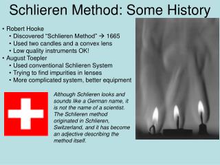
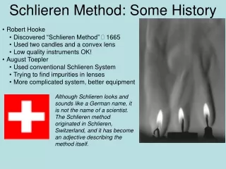
Schlieren Visualization • optical techniques have been used for decades to study inhomogeneous media • Robert Hooke (1635-1703) – “Father of the optics of inhomogeneous media”, invented the schlieren method • many different optical techniques for studying fluid flow • will focus on the classic schlieren technique Schlieren image of explosion in hydrogen-air
Basic Concepts: Light Propagation Through Inhomogeneous Media A: atmosphere is inhomogeneous – disturbances due to turbulence etc. change the air density → change in the refractive index → rays of starlight bend, wave front of the light is wrinkled → star not a point, but fluctuates (“twinkles”) on the time scale of the atmospheric disturbances allow us to see the phase differences in light Schlieren and Shadowgraph Techniques Q: Why do stars “twinkle”?
Basic Concepts: Light Propagation Through Inhomogeneous Media Refractive Index:describes how the speed of light changes upon interacting with matter Gases: linear relationship between nand the gas density
Basic Concepts: Light Propagation Through Inhomogeneous Media Refractive index only very weakly dependent on density → k = 0.23 cm3/g = 2.3 x 10⁻⁴ m3/kg Increase air density by two orders of magnitue → 2.3% increase in n! Require very sensitive optics!
Basic Concepts: Light Propagation Through Inhomogeneous Media What does “schlieren” mean? • Schliere (singular of schlieren): • German for “streak,” “striation,” or “cord” • gradient disturbance of inhomogeneous transparent media • object that has a gradient in the index of refraction, i.e.
Basic Concepts: Light Propagation Through Inhomogeneous Media Example schliere: Laminar Candle Plume The gas in the plume is hotter and less dense than the surrounding gas, so r2 and therefore r1 r1 y producing a gradient in the x-direction x
Basic Concepts: Light Propagation Through Inhomogeneous Media Increasing n Planar wave front Dz = cDt = (c0/n)Dt y1 Dz1 Rays (normal to wave front) y2 Dz2 Dz1 = (c0/n1)Dt and Dz2 = (c0/n2)Dt Since n2 > n1, c2 < c1 so Dz2 < Dz1 t = 0 t = Dt y x Negative vertical refractive-index gradient dn/dy < 0 z
Basic Concepts: Light Propagation Through Inhomogeneous Media Increasing n RESULT: Refracted wave front Huygen’s Principle: Light rays, always normal to the local speed of light, are bent toward the zone of higher refractive index (zones of higher density in gases). t = Dt y Negative vertical refractive-index gradient dn/dy < 0 x z
Basic Concepts: Light Propagation Through Inhomogeneous Media De Dy Distance wave front moves in time Dt: dn/dy < 0 y2 (c0/n2)Dt Dz Refraction angle: y z2 z1 De y1 Also: y x z
Basic Concepts: Light Propagation Through Inhomogeneous Media De Dy dn/dy < 0 y2 (c0/n1)Dt Dz y z2 z1 De Because e is a very small angle, it is approximately equivalent to dy/dz, the slope of the refracted ray. y1 y and x z Curvature of refracted ray
Basic Concepts: Light Propagation Through Inhomogeneous Media De Dy So the angular ray deflection in the x and y directions are: dn/dy < 0 y2 (c0/n1)Dt Dz and y z2 z1 De For a 2D schliere of length L along the optical axis (z): y1 and y x Refraction caused by gradients of n, not overall level of n! z
Shadowgraphy Only need a light source, a schlieren object, and screen on which the shadow is cast screen extra illumination e * less illumination schliere point light source lens e * point light source Screen Denser sphere (i.e. a bubble) screen
Shadowgraphy Dark circle due to light refracted from outline of sphere Light circle due to refracted light from the outline illuminating this part of the screen Gradient back to background illumination due to non-uniform refraction of rays as the light wave travels down the optical axis (x) Screen
Shadowgraphy • see some shadow, but don’t get outline of the schliere • as move down optical path (z-direction), so all rays shift the same! y Uniform shift of illumination z • as move down optical path (z-direction), so rays shift non-uniformly y Nonuniform illumination Variation of gradients critical! z
Example Shadowgraphs He/N2 mixing layer (Settles 2001) Sphere flying at M=1.7 (Merzkirch 1987) Shock wave diffraction around wedge (Settles 2001) Oil globs in water (Settles 2001)
Shadowgraphy vs. Schlieren Imaging Schlieren Imaging Shadowgraphy Focused optical image formed by a lens Not an image but a shadow Requires cutoff of the refracted light No cutoff of refracted light Illuminance level responds to ∂n/∂x and ∂n/∂y Responds to second spatial derivative, ∂2n/∂x2 and ∂2n/∂y2 Schlieren image displays the deflection angle e Shadowgraph displays ray displacement More sensitive in general Less sensitive except for special cases (e.g. shock waves) More difficult to set up – use lamps, mirrors, lenses Extremely easy to setup, occurs naturally
Schlieren System – Point Light Source screen lens lens focused back to same point on screen * point light source deflected rays miss the focus schliere in test section • merely a projector, imaging opaque objects in the test section
Schlieren System – Point Light Source screen lens lens * Brighter point on screen point light source knife-edge schliere in test section • translating phase difference causing a vertical gradient ∂n/∂y to amplitude of light on the screen • refracts many rays in many directions – all downward deflected rays get blocked, painting at least a partial picture • gives black and white image
Schlieren System – Extended Light Source screen lens lens extended light source knife-edge • the light source is first collimated by a lens then refocused by the second lens • an inverted image of the light source is formed at the knife-edge • the extended light source can be considered as an array of point sources – each “point source” forms a schlieren beam that focuses to a corresponding point in the light source image (extreme rays shown in cartoon above) • knife-edge blocks a portion of the image of the extended light source • another lens focuses an inverted image of the test area on the screen
Schlieren System – Extended Light Source screen lens lens extended light source knife-edge • each “point source” in the extended light sources illuminates every point in the test section → each point in test section is illuminated by rays from the entire extended source • when focused to knife-edge, each point in test section produces an entire “elemental” source image to the “composite” image at the knife-edge • e.g. if insert a pinhole in the test section, would still see an image of the extended source, but much weaker in intensity than the “composite” image
Schlieren System – Extended Light Source screen lens lens extended light source knife-edge • IMPORTANT POINT: • with no schliere present, if we advance the knife-edge to block more the “composite” image of the extended light source → block each “elemental” source image equally therefore blocking equal amount of light from every point in the test area Screen darkens uniformly! This is how you know your alignment is good and that you are at the true focus!
Schlieren System – Extended Light Source screen lens lens extended light source knife-edge NOW PLACE A SCHLIERE IN THE TEST AREA • consider one point in the test area to be subject to refraction by the schliere • since all of the “point sources” on the extended light source contribute a ray to this point, a group of rays from all “point sources” is deflected (dashed lines in cartoon) • this group of rays are focused to produce an “elemental” image of the light source at the knife-edge but the image is displaced due to the refraction • the group of rays is returned to the same relative position on the screen by the third lens → true image of the schliere at the screen
Schlieren System – Extended Light Source • the displacement of the “elemental” source image separates the rays refracted by the schliere from the rays that provide the background illuminance • because the refracted light is separated, can have a different amount of cut-off by the knife edge → recombined in the schlieren image at the screen → variations in the illumination with respect to the background schlieren image that shows the shape and strength of the schliere Many points of varying illuminance Weak source image displaced by schlieren object Note: using an extended light sources gives continuous gray-scale schlieren images! Undisturbed composite source image Knife-edge
Schlieren System – Extended Light Source Sensitivity: differential illuminance at an image point background illuminance focal length of the schlieren lens refraction angle Constrast: Sensitivity: Weak source image displaced by schlieren object Larger focal length = better sensitivity More obstruction of source image = better sensitity Undisturbed composite source image Knife-edge
Z-Type Schlieren Arrangement light source condenser lens pinhole or slit parabolic mirror parabolic mirror test area knife-edge camera Most common arrangement: easy to set-up, allows for a schlieren mirror with long focal length (high sensitivity) and large field-of-views
Cool Schlieren Images Bullet and candle flame (Settles 2001) Glass fibers (Settles 2001) Projectile fired at Mach 4.75 in reactive H2/air mixture – cyclic detonation behind the shock (Settles 2001)
Cool Schlieren Images Removing frozen pizza from case (Settles 2001) Blackjack dealer and players (Settles 2001) Space heater (Settles 2001)
Cool Schlieren Images Image of a T-38 at Mach 1.1 (Leonard M. Weinstein, NASA Langley Research Center) – taken using a telescope, the sun, and a cutoff, field of view of 80 m!
Cool Schlieren Images Color schlieren of the space shuttle orbiter in supersonic wind tunnel test (Settles 2001) Color schlieren of a gun firing 0.22 caliber bullet (Settles 2001) 3D schlieren of a glass figurine (Settles 2001)
Important Equations Object (FOV) Lens 1 Lens 2 Knife-edge Object image Inverted object image y0 yI2 yI1 x1 f2 f1 x2 x3 x4 Equations: Constraints: Gaussian Lens Equation: For Real Image: Table Size: Magnification: Total Magnification where L is limited by the size of the optics table
Important Equations Object (FOV) Lens 1 Lens 2 Knife-edge Object image Inverted object image y0 yI2 yI1 x1 f2 f1 x2 x3 x4 Must Satisfy: Under the Constraints: SUMMARY
How My Schlieren Setup Works Flat mirror Flat mirror Baffle (to block stray light) Concave mirror (schlieren lens) f = 1000 mm Test section (1” Ø field-of-view) Aperture (to make 1” Ø beam) Flat mirror Achromatic lens (to collimate the light) f = 200 mm Vertical slit (razor blades) Optical assembly Knife-edges (razor blades) Light source (Xe arc lamp) High-speed camera (no additional focusing lens used) Flat mirrors
How My Schlieren Setup Works 1 2 Camera Side: Schlieren “Lens” (concave mirror) Inverted object image on camera CCD Object (1” Ø field-of-view) Knife-edges yI yO f f x1 x2 Equations: Knowns: Unknowns:
How My Schlieren Setup Works 3 3 1 1 2 2 2 into Invert Solve for x1: Then from : Remember: Sensitivity is proportional to the focal length so f should be as large as possible!
Setting Up a Schlieren System:Step-by-Step (1) optical axis (z) laser ruler or height gauge x z Step 1: Calculate the required distances between he object, schlieren lens, focusing lens, and camera based on the equations on the previous slide and the focal lengths of your lenses Step 2: Set up the light source, any flat mirrors, and test section with windows in place if applicable Step 3: Set up a laser in the place where the camera will go Step 4: Turn on the laser and ensure that the beam is straight in both the vertical and horizontal directions along the optical axis (line to next mirror) Side View Top View optical axis (z) y laser right angle ruler
Setting Up a Schlieren System:Step-by-Step (2) window Incident laser beam piece of paper reflection Step 5: Adjust any mirrors on this side of the set-up to direct the laser to the test section, ensuring that the beam stays the same height the whole way (use a ruler or a height gauge to test this at every mirror) Step 6: If there are windows on the test section, check for reflections to ensure the laser is perpendicular to the windows Tip 1: Try to keep the laser dot as close to the center of the mirrors as possible Tip 2: The laser light corresponds to approximately the center of the ultimate light beam, so locate the laser beam through the test section where you want the center of the light beam Tip 1: Use a piece of paper to probe all around the incident beam – any reflections will show up on the paper Tip 2: When it is properly aligned, when you look through the windows all the laser dots will appear in a straight line through the glass
Setting Up a Schlieren System:Step-by-Step (3) Step 7: Adjust any mirrors on the light-source side to direct the laser beam to the light source, ensuring the beam stays the same height and is centered on the mirrors Step 8: Adjust the height of the light source so that it is at the same height as the laser beam Step 9: Remove the cover of the light source (make sure it is unplugged and cold!) so you can see the filament or arc bulb. Step 10: Use the controls on the light source to move the filament or bulb until the laser light hits the center of the filament or bulb. Check for reflections. Tip 1: The two most common types of light sources are filament and arc light sources, and there are often lenses mounted on the front Tip 2: First, adjust the height of the light source so that the laser beam is centered on the lens on front of light source if present Tip 3: Check for reflections from the lens using the method described before – adjust light source orientation to minimize relfections
Setting Up a Schlieren System:Step-by-Step (4) Step 11: Once alignment of the laser, mirrors, and light source is complete, be sure to secure all the optics in place. Step 12: One-by-one, add the lenses to the setup. Step 13: Once the alignment is complete, secure well all of the optical components. Step 14: Replace the laser with the camera, place the knife-edge at the approximate location of the focus of the schlieren lens, and turn on the light source. Tip 1: The laser light should go through the center of the lens. Tip 2: Check for reflections using the method described before (probe around the beam with a piece of paper between the incident laser beam and the lens). Get rid of reflections by adjusting the height of the lens and angle of the lens with respect to the laser. Now the REAL work begins! Remember, the best tool for setting up a good schlieren system is PATIENCE!
Setting Up a Schlieren System:Step-by-Step (5) lens 1 lens 2 light source aperture f1 f2 Step 15: Starting at the light source, very carefully make slight changes to the focusing lens (if one is not included on the light source) to focus the light source down onto the pin-hole or slit. Step 16: Using a precision translation stage, adjust the distance between the pin-hole or slit and the collimating lens until the beam is collimated. Use an aperture if desired to define the size of the beam Tip 1: Position the collimating lens (lens 2) one focal length (f2) from the pin-hole or slit first. Tip 2: Put up a piece of paper a good distance from the lens, then carefully adjust the distance between lens 2 and the pin-hole/slit until the beam on the paper is the same size as at the aperture – then the light is collimated!
Setting Up a Schlieren System:Step-by-Step (5) Step 17: After the beam has been collimated, if it is not in the location where you want it in the test area, make adjustments to move the beam. Step 18: Follow the same procedure to position the image correctly on the camera, heeding the Tips 1 and 2. Step 19: Find the approximate location of the focus of the schlieren lens, and place the knife-edge there on translation stages. Step 20: Step the knife-edge in/up to block part of the light – if you are at the focus, the background will become dimmer uniformly. Adjust the location of the knife-edge using the translation stages until you find the focus. Tip 1: Make horizontal adjustments by moving the mirrors – NOT tilting the mirrors, but actually moving them horizontally. It is a good idea to mount the mirrors on translation stages to allow for this. Tip 2: Make vertical adjustments by changing the aperture (if you are using one) if possible; if not, change the height of both the lenses and the light source.
References & Where to Buy Optics Reference Books on Schlieren Methods: G. S. Settles. Schlieren and Shadowgraph Techniques. Springer-Verlag, 2001. W. Merzkirch. Flow Visualization. 2nd Ed. Academic Press, Inc., 1987. Where to purchase optical components: Thorlabs, Inc http://www.thorlabs.com Newport http://www.newport.com Edmund Optics http://www.edmundoptics.com CVI Melles Griot http://www.cvimellesgriot.com