Download
1 / 12
270 likes | 1.02k Views
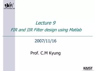
Lecture 9 FIR and IIR Filter design using Matlab. 2007/11/16 Prof. C.M Kyung. FIR and IIR Filter. GOAL Linear-Time-Invariant (LTI) system and Impulse response z-Transform Characteristics of FIR and IIR filters Design procedure of FIR and IIR filters. FIR and IIR Filter. LTI System

E N D
Lecture 9 FIR and IIR Filter design using Matlab 2007/11/16 Prof. C.M Kyung
FIR and IIR Filter • GOAL • Linear-Time-Invariant (LTI) system and Impulse response • z-Transform • Characteristics of FIR and IIR filters • Design procedure of FIR and IIR filters
FIR and IIR Filter • LTI System • Input (x(t) or x[n]) and Output (y(t) or y[n]) is defined first • For a given system, it can be either LTI or non-LTI depending on how we define the input and output. • Linearity • For arbitrary and , the output of the system for is the sum the output for and . (superposition) • Time-invariance • Time-shift in input results in time-shift in output by same amount for time-invariant systems.
FIR and IIR Filter • Impulse Response • Definition • Impulse response is the output of the system when impulse signal or is applied as the input of the system. • Importance • Impulse response “fully describes” the system if the system is LTI. • Why and how? • Why the impulse response CANNOT fully describe a non-LTI system? • Fourier transform of the impulse response shows the characteristic of the system is frequency domain.
FIR and IIR Filter • z-Transform • Definition • The z-transform of a sequence is defined as • Example • For , , • Note • z-transform is reduced to discrete-time Fourier transform (DTFT) if is substituted by . • This means that z-transform on the unit-circle on the complex plain is same as DTFT. • Laplace Transform CTFT ~ z-Transform DTFT
FIR and IIR Filter • Ideal frequency-selective filter • A filter whose frequency response is unity over a certain frequency range and zero for other frequencies. • Frequency response of an ideal low-pass filter • However, an ideal low-pass filter is noncausal.
FIR and IIR Filter • FIR / IIR filter • Definition • If the length of the impulse response is finite, the filter is an FIR (finite impulse response) filter. Otherwise, the filter is an IIR (infinite impulse response) filter. • FIR • Inherently BIBO (bounded-input, bounded-output) stable • Nonzero pole does not exist in its transfer function • Easy to implement • Can be designed to have linear phase property • IIR • Sometimes unstable • Nonzero pole exists in its transfer function • Lower filter order than a corresponding FIR filter • Usually have nonlinear phase property
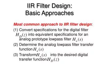
FIR and IIR Filter • Filter Design Procedure • Design continuous-time IIR filter • Obtain desired using Butterworth, Chebyshev methods • Convert it to discrete-time IIR filter using impulse invariance • Impulse invariance : , if , • Obtain discrete-time FIR filter by windowing the IIR filter • Windowing : • Commonly used windows : rectangular, Bartlett, Hanning, Hamming, Blackman, Kaiser, … • However, windowing does not give the optimum solution and other approaches can be used.
FIR and IIR Filter • Frequency response of various filters
FIR and IIR Filter • Problem Statements • Design several types of FIR and IIR filters • IIR – butterworth, chebyshev type1, chebyshev type 2, … • FIR – using different windows ( Hamming, Hanning, Bartlett, … ) • Remove the noise in acoustic signal using the filters • What are the differences between the filters ? • Understand the effect of sampling frequency on the sampled signal distortion (aliasing)
FIR and IIR Filter • Experiment Requirements • PC • Matlab software (with signal processing toolbox)
FIR and IIR Filter • References • Fundamentals of Signal & System using the web and matlab - Edward W. Kamen, Bonnie S. Heck • Discrete-Time Signal Processing - Alan V. Oppenheim, Ronald W. Schafer • http://www.mathworks.com/access/helpdesk/help/toolbox/signal/filterde.html