Download
1 / 38
470 likes | 896 Views
Chapter 10 Switching DC Power Supplies. One of the most important applications of power electronics. Linear Power Supplies. Very poor efficiency and large weight and size. Switching DC Power Supply: Block Diagram. High efficiency and small weight and size.

E N D
Chapter 10 Switching DC Power Supplies • One of the most important applications of power electronics Chapter 10 Switching DC Power Supplies
Linear Power Supplies • Very poor efficiency and large weight and size Chapter 10 Switching DC Power Supplies
Switching DC Power Supply: Block Diagram • High efficiency and small weight and size Chapter 10 Switching DC Power Supplies
Switching DC Power Supply: Multiple Outputs • In most applications, several dc voltages are required, possibly electrically isolated from each other Chapter 10 Switching DC Power Supplies
Transformer Analysis • Needed to discuss high-frequency isolated supplies Chapter 10 Switching DC Power Supplies
PWM to Regulate Output • Basic principle is the same as discussed in Chapter 8 Chapter 10 Switching DC Power Supplies
Flyback Converter • Derived from buck-boost; very power at small power (> 50 W ) power levels Chapter 10 Switching DC Power Supplies
Flyback Converter • Switch on and off states (assuming incomplete core demagnetization) Chapter 10 Switching DC Power Supplies
Flyback Converter • Switching waveforms (assuming incomplete core demagnetization) Chapter 10 Switching DC Power Supplies
Other Flyback Converter Topologies • Not commonly used Chapter 10 Switching DC Power Supplies
Forward Converter • Derived from Buck; idealized to assume that the transformer is ideal (not possible in practice) Chapter 10 Switching DC Power Supplies
Forward Converter: in Practice • Switching waveforms (assuming incomplete core demagnetization) Chapter 10 Switching DC Power Supplies
Forward Converter: Other Possible Topologies • Two-switch Forward converter is very commonly used Chapter 10 Switching DC Power Supplies
Push-Pull Inverter • Leakage inductances become a problem Chapter 10 Switching DC Power Supplies
Half-Bridge Converter • Derived from Buck Chapter 10 Switching DC Power Supplies
Full-Bridge Converter • Used at higher power levels (> 0.5 kW ) Chapter 10 Switching DC Power Supplies
Current-Source Converter • More rugged (no shoot-through) but both switches must not be open simultaneously Chapter 10 Switching DC Power Supplies
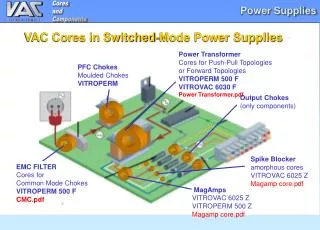
Ferrite Core Material • Several materials to choose from based on applications Chapter 10 Switching DC Power Supplies
Core Utilization in Various Converter Topologies • At high switching frequencies, core losses limit excursion of flux density Chapter 10 Switching DC Power Supplies
Control to Regulate Voltage Output • Linearized representation of the feedback control system Chapter 10 Switching DC Power Supplies
Forward Converter: An Example • The switch and the diode are assumed to be ideal Chapter 10 Switching DC Power Supplies
Forward Converter:Transfer Function Plots • Example considered earlier Chapter 10 Switching DC Power Supplies
Flyback Converter:Transfer Function Plots • An example Chapter 10 Switching DC Power Supplies
Linearizing the PWM Block • The transfer function is essentially a constant with zero phase shift Chapter 10 Switching DC Power Supplies
Gain of the PWM IC • It is slope of the characteristic Chapter 10 Switching DC Power Supplies
Typical Gain and Phase Plots of the Open-Loop Transfer Function • Definitions of the crossover frequency, phase and gain margins Chapter 10 Switching DC Power Supplies
A General Amplifier for Error Compensation • Can be implemented using a single op-amp Chapter 10 Switching DC Power Supplies
Type-2 Error Amplifier • Shows phase boost at the crossover frequency Chapter 10 Switching DC Power Supplies
Voltage Feed-Forward • Makes converter immune from input voltage variations Chapter 10 Switching DC Power Supplies
Voltage versus Current Mode Control • Regulating the output voltage is the objective in both modes of control Chapter 10 Switching DC Power Supplies
Various Types of Current Mode Control • Constant frequency, peak-current mode control is used most frequently Chapter 10 Switching DC Power Supplies
Peak Current Mode Control • Slope compensation is needed Chapter 10 Switching DC Power Supplies
A Typical PWM Control IC • Many safety control functions are built in Chapter 10 Switching DC Power Supplies
Current Limiting • Two options are shown Chapter 10 Switching DC Power Supplies
Implementing Electrical Isolation in the Feedback Loop • Two ways are shown Chapter 10 Switching DC Power Supplies
Implementing Electrical Isolation in the Feedback Loop • A dedicated IC for this application is available Chapter 10 Switching DC Power Supplies
Input Filter • Needed to comply with the EMI and harmonic limits Chapter 10 Switching DC Power Supplies
ESR of the Output Capacitor • ESR often dictates the peak-peak voltage ripple Chapter 10 Switching DC Power Supplies