Download
1 / 43
430 likes | 536 Views
A detailed overview of the OPOLES system components for enhanced positional light communication. Includes GPS, RF, and optical modules with detailed technical specifications and applications. Ideal for team-based player alignment in games.

E N D
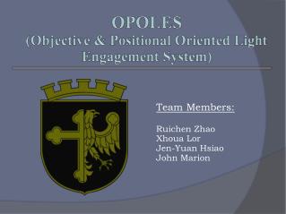
OPOLES (Objective & Positional Oriented Light Engagement System) Team Members: Ruichen Zhao Xhoua Lor Jen-Yuan Hsiao John Marion
Systems Diagram GPS Expandable Modules Main Board Optical Receiver Primary User I/O Optical Transmitter RF Transciever
Main Board I/O Ports Microcontroller Circuitry (MSP430) 6-10V Rechargeable Battery Power Regulator Driver Circuitry (Darlington Arrays) Optical Power Ports
LCD Display • Free, recycled from MilesTag taggers. • Four pin control. • Reset and Enable Pins.
GPS • Global Positioning System • MN5010HS • SiRF Binary Protocol • Standalone chip that streams 32bit XYZ positional data.
GPS Block Main Board Power Regulator I/O Ports Power Regulator GPS Chip Chip Antenna
Components For GPS • GPS Micro-Mini • From Sparkfun. • Note have chip as well for second revision based on sparkfun model. • Prebuilt version is more expensive. • Connector Ports • Connect and disconnect from main board. • Plug and Play (kind of). • Antenna
RF Link • Radio Frequency Communication. • The radio front end uses GFSK modulation. • The channel occupies a bandwidth of less than 1MHz at 250kbps • The ANT1 and ANT2 output pins provide a balanced RF output to the antenna • Zo = 15Ω+j88Ω
RF Block Main Board Power Regulator I/O Ports Power Regulator RF transceiver Chip Antenna
Dipole Antenna • Frequency: 2.4-2.5 GHz • Gain: 3.2 dBi • Impedance: 50ohm • VSWR < 1.9 • Polarization: Vertical • Radiation: Omni
Components For RF Link • Transceiver nRF24L01+ Module with Chip Antenna. • From Sparkfun. • Connector Ports • Connect and disconnect from main board. • Plug and Play (kind of). • Resistors/Capacitors/Inductors • Biasing and Impedance Matching. • Antenna • Chip antenna does not work well in use.
Optical Communication • PWM Infrared light • Encodes a bit stream of data • Added 455kHz communication
Optical Block Optical Transmitter TSAL (IR Diode) Main Board Tricolor LED I/O Port I/O Port 455kHz Receiver 56kHz Receiver Darlington Driver 38kHz Receiver
Modulated Output • Using PWM (Pulse Width Modulation) • We output a fc=40, 56 or 455 kHz square wave of the IR light wave(950 nm = 316THz). • 24 periods of 1/fc for a zero, 48 periods for a 1 and a 96 periods for a header. • Each pulse is separated by 24 periods of off time. From Vishay Documentation
Transmitted Light Wave This is an example of a what is actually propagated through the air. 5 periods of pulsed IR.
Demodulation Reciever • TSOP sensor has built in demodulator. • All we see at the processor is a PWM signal that represents a bit stream. • Inverted signal From Vishay Documentation
Pulse Width Example • Example Signal from MilesTagwebsite. • We are using this scheme scaled to our carrier frequencies. • At 455kHz we can fit in over ten times the data in the same time.
Tested Example • Here is an example of what we generate • Binary 01 • Transmitted • Received 0 1 0 1
TSOP Functional Diagram From Vishay Documentation
TSOP Block Diagram From Vishay Documentation
TSOP Application Circuit From Vishay Documentation
Power Driver ULN2803 • Isolates Microcontroller from sensors. • For Tricolor LEDs and Sensors. • 8 Darlington Pairs Per Package. • 500mA per Darlington Pair. • Plenty of leeway Sensors max rating 200mA. • LEDs max on a pair would be 80mA.
Power Driver ULN2803 From TI Documentation
Power Driver ULN2803 Single internal Circuit With on/off modeled + Driven System model
Sensor Board Ports Breakdown • 9 Selection bits for color of each sensor area. • Red Green Blue (Any Combo!) • Head, Front and Back can light differently. • Select with switches or Jumpers. • 3 selection bits for selection of which TSOP to use. • 455kHz/56kHz/38kHz. • 3 inputs from sensors. • Head, Front or Back. • Select with switches or Jumpers • Sensors for each section in parallel.
Components on Sensor Boards • TSOPs • 38kHz, 56kHz and 455kHz sensors. 1 each. • Tri-Color LED • Common Anode (changed to work with Driver). • Decoupling Capacitor • Stabilize Power to TSOP. • Resistors • Current limiting for Sensors and LEDs. • Ports • 1 in, 1 out in parallel.
Components on Transmitter • TSAL6100 • Highly directional IR LED • TSAL driver MOSFET (optional but likely) • Muzzle Flash • Standard white LED. • Resistors • Current limiting for the LED. • Cable • Run to main board
Primary I/O Components • Display (LCD) • 8X2 Char. LCD or one available from lab • Serial Interface • Need driver circuit. • Sound • Peizo Buzzer • ISD Sound Chip • Controls (Keypad/Buttons) • Directional Buttons. • Trigger • Reload • Key switch • Team color selecting LEDs • Tell a player which sensors are active • Tell players which team a player is aligned with. • Other game specific options.
Goals for Milestone I • Working GPS communication • Sensors communicate correctly with microcontroller • Microcontroller interrupts correctly • Revision 1 of PCB completed and integrated
Goals for Milestone 2 • Final revision of PCB is complete • Working RF link • All basic functionalities complete • Working on documentation • Possibly working on audio feedback • If time allows
Goals for Expo • Two working prototypes • Communicate with each other • Has a game play function set up • Completed documentation • User Manual • Technical Manual
Division of Labor • TJ: • RF interface • Hardware construction • Soldering • Wiring • Richard: • Coding • Protocol Practicality • John: • Protocols • Documentation • Sensor boards • Design & Etching • Jen-Yuan: • Schematics • Board Layout • GPS