Introduction to SPICE (Version16.2)
250 likes | 417 Views
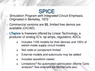
Introduction to SPICE (Version16.2). Prof. Shahrokh Ahmadi ECE002. What is SPICE?. SPICE stands for Simulation Program with Integrated Circuit Emphasis This software is widely used for analog and digital circuit design and also for educational purposes.

Introduction to SPICE (Version16.2)
E N D
Presentation Transcript
Introduction to SPICE(Version16.2) Prof. Shahrokh Ahmadi ECE002
What is SPICE? • SPICE stands for Simulation Program with Integrated Circuit Emphasis • This software is widely used for analog and digital circuit design and also for educational purposes
Start > Cadence SPB 16.2 > Design Entry CIS To Start the Program…
Place components using this icon Component List Component Library In the case that you do not see the library list, please load the library list from here
R/Analog = Resistor VDC/Source = DC Voltage Source VSIN/Source = AC Voltage Source For Wiring use this icon
Wiring The Red Dot means a Node where the wiring is correct!
Setting up the Voltage Source By Clicking on the component value you can modify the value! (if you click on the component itself, you will be able to change more properties).
Placing the Probes Current Probe Voltage Probe
Placing the Probes Do not forget to put the ground in your circuit!
Start Simulating … Press this one to start… Then, enter a name for your simulation…
Time duration of the simulation Now, you are good to go! Press the green “play” button to start the simulation!
If you want to rerun the simulation and you want to change the simulation properties, you can use this icon to bring up the menu!
Use the same procedure to simulate a Diode! For D1N4002 diode the cutoff voltage is around ~ 0.6 Volts
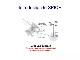
Sin Waves FREQ=1/T T VAMP VOFF Offset voltage