Download
1 / 17
190 likes | 457 Views
Particle-Driven Plasma Wakefield Acceleration. James Holloway University College London, London, UK PhD Supervisors: Professor Matthew wing University College London, London, UK Professor Peter Norreys Central Laser Facility, Rutherford Appleton Laboratory, UK. Current RF Accelerators.

E N D
Particle-Driven Plasma Wakefield Acceleration James Holloway University College London, London, UK PhD Supervisors: Professor Matthew wing University College London, London, UK Professor Peter Norreys Central Laser Facility, Rutherford Appleton Laboratory, UK
Current RF Accelerators Accelerate particles within a metal cavity. Accelerated using an alternating electric field. Electric fields greater than ~100 MVm-1 will ionize the metal itself. --> To reach higher particle energies one has to increase the length over which the particles are being accelerated. Plasmas can support higher electric fields. A plasma of number density ne = 1014 cm−3 can support electric fields of E = 1 GVm−1. The Livingston plot shows the switch on time of hadron and lepton colliders at the energy frontier as a function of achieved energy.
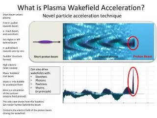
Novel particle acceleration technique What is PWA? + + - - + - + + + Short proton beam Proton Beam Neutral plasma • Can also drive wakefields with • Electrons • Photons • Positrons • Muons (in principle)
The Plasma Plasma frequency Interstellar plasma Lightning Inertial confinement fusion Maximum supportable E field
The Diamond Light Source • The Diamond light source at RAL uses a 3 GeV electron beam to generate soft x-rays. • The beam is generated by a 90 KeV electron gun that injects them into the Linac, which brings • it to ~ 100 MeV. The booster then brings it to 3 GeV then finally the storage ring maintains the • energy whilst cooling the beam. • Beam length: σz = 2.6 cm -> too long to effectively drive a wakefield. (λp ~ mm). • A proof of principle experiment has been proposed • to micro bunch the beam using the self modulation • instability, with the future intent to use the treated • beam to: • Create a higher energy electron beam • Create a poor mans FEL using betatron • oscillations within the wake • Imprint the modulated density profile of the • Diamond beam onto a proton beam, seeding • the modulation onto the proton beam The Diamond light source, RAL.
Affects long drive beams. The Self-Modulation Instability + + - - + - + + + + + - - + - + + + Long proton beam Neutral plasma Microbunches are spaced λp apart. Charge density increased. Micro bunch lengths are much closer to the ideal driver length of: λp /π These properties then allow the modulated beam to drive a wakefield much more effectively. Neutral plasma Self-modulated driver beam
Linac 90 KeV Pictures by Michael Bloom, Imperial College.
Booster 158m circumference Pictures by Michael Bloom, Imperial College.
The Diamond Experiment Serveral slides of tour of Diamond! Transfer Line Pictures by Michael Bloom, Imperial College.
The Diamond Experiment Serveral slides of tour of Diamond! Storage Ring Pictures by Michael Bloom, Imperial College.
Simulations • Diamond Booster Parameters • Energy 3 GeV • Geometric emittance 140 nm rad • Rms relative energy spread 0.0007 • Rms bunch length 2.6 cm • Charge up to 2 nC • Simulations so far: • Untreated Diamond beam from the booster • -> Drove a weak wakefield • Cooled beam (2.7 nm rad) from the storage ring • -> Drove a weak wakefield • Radially compressed beam – using quadrupole • -> Filamentation instability dominated • Cut beam • -> Drove a weak wakefield. E = 70 KVm-1 • Seeded beam – using an ideal driver • Typical simulation parameters: • 4320 x 320 grid. ~ 107 particles • 127 cores over 4 days • ne = 1.11 x 10²⁰ m-3 • -> λp = 3.17mm
Simulations The untreated Diamond beam: Set: --> σr = 1.58 mm T = 1 x 10⁸ K • Energy 3 GeV • Geometric emittance 140 nm rad • Rms relative energy spread 0.0007 • Rms bunch length 2.6 cm • Charge up to 2 nC Rear view Side View Before: After: No Micro bunching Mild filimentation Simulation of the untreated Diamond beam.
Simulations Radially compressed Diamond beam. -> Higher charge density drives a stronger wakefield. Set: --> σr = 0.158 mm T = 1 x 10¹⁰K Filamentation destroys the beam. Cannot compress smaller than σr~ 1.58 mm. Simulation of the untreated Diamond beam.
Simulations Initial wakefield driven by ultra short pulse. σr = σz = 0.144 mm. Charge = 102 nC. nbpeak = 5 x 10¹⁸ m-3 Diamond beam then propagates in that wakefield and becomes micro bunched. E = 3 MVm-1 Simulation of the Diamond beam propagating with a wakefield.
Upcoming Simulations • Next set of simulations: • Small parameter scan over intensities of seeding laser pulse • Modulated Diamond bunch into second plasma stage • Modulated Diamond bunch co-propagating with non-modulated proton bunch. • Inject witness electron beam and use motion to calculate synchrotron radiation • Laser Parameters: • λ = 1 μm. • Spot size = ~50 μm Diameter • I = 1013– 1015Wcm-2 • Pulse length ~ 500 fs If our simulations demonstrate modulation of the Diamond beam is feasible and we secure the beam time and the funding then this experiment should go ahead in 2012.