Download
1 / 46
460 likes | 743 Views
Proton Driven Plasma Wakefield Acceleration – AWAKE – Project. Outline. Introduction Plasma Wakefield Acceleration Mandate of the AWAKE project AWAKE Project Structure and Organization AWAKE Project Studies. Why.

E N D
Proton Driven Plasma Wakefield Acceleration – AWAKE – Project
Outline • Introduction • Plasma Wakefield Acceleration • Mandate of the AWAKE project • AWAKE Project Structure and Organization • AWAKE Project Studies
Why In recent years several Laser or Electron-driven Plasma Wakefield experiments: • E.g. SLAC (2007) 50GV/m over 0.8m with electron-driven PWA some electrons doubled energy from 42GeV to 80GeV Advantage of proton driven plasma wakefield acceleration: • high stored energy available in the driver. • Existing proton bunches carry many kJ of stored energy (high power lasers carry 1-5 J) • Reduces drastically the number of required driver stages. Proof-of principle demonstration experiment proposed at SPS: • first beam-driven wakefield acceleration experiment in Europe, and the first Proton-Driven PWA experiment worldwide.
Introduction • Letter of Intent: positive review in SPSC October 2011 • Research Board December 2011: • submit Conceptual Design Report during following year • June 2012: • Official CERN AWAKE project (including project-budget) with mandate sent by S. Myers to DHs. • CERN project leader (E.G.) • organize CERN efforts to produce parts of CDR under CERN responsibility • CDR includes detailed budget, CERN manpower and schedule plans for design, construction, installation and commissioning. • Deliverables: • End 2012: preliminary report summarizing the ongoing study to the A&T sector Management • Q1 2013: Conceptual Design Report to the A&T sector Management. AWAKE collaboration: 25 institutes
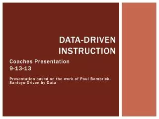
- - - - - - - - - - - - - - - - - - - - - - - - - - - - - - - - - - - - - - - - - - - - - - - - - - - - - - - - - - - - - - - - - - - - - - - - - + + + + + + + + + + + + + + + - + + + + + + + + + + + + + + + - - - - - - - - - + + + + + + + + + + + + + + + + - - + + + + + - + + + + + - + + + + - + - + - + + + + + - + + + + + + + + + + + + + + + + + + + - - - - - - - - - - - - - - - - - - - - - - - - - - - - - - - - - - - - - - - - - - - - - - - - - - - - - - - - - - - - - - - Ez Principle of Plasma Wakefield Acceleration I Drive beam Produce an accelerator with mm (or less) scale ‘cavities’ • Space charge of drive beam displaces plasma electrons. • Plasma ions exert restoring force. np Plasma electrons oscillate with: Plasma wavelength: Nprotons/bunch e.g. for typical plasma density of np= 1015cm-3 lp =1mm sz (rms bunch length) Ez,max = Maximal axial electric field: With plasma wavelength of 1mmalso drive beam rms length of 1mm
Principle of Plasma Wakefield Acceleration II • SPS beam: rms length of ~12cm • But strong self-modulation effect of proton beam due to transverse wakefield in plasma • Starts from any perturbation and grows exponentially until fully modulated. • Ultra-short bunch slices are naturally produced with a spacing of plasma wavelength lp. p-beam density profile after 4.8m propagation in plasma. • Seeding of bunch modulation with laser: • Ionization of Plasma • Produce start of bunch-modulation in a controlled way gas Plasma Intense short laser pulse co-propagates with proton bunch. plasma get ionized at fixed position. generates large perturbation and seeds modulation. proton bunch laser pulse
Principle of Plasma Wakefield Acceleration III Inject electron beam to accelerate Electron bunch injected off-axis at an angle and some metresdownstream along the plasma-cell: merges with the proton bunch once the modulation is developed. Longitudinal electric field generated in plasma as function of propagation distance. 100-1000MV/m. Particle-in-cellsimulationspredictaccelerationofinjectedelectronstobeyond 1 GeV.
Experimental Layout Laser e- spectrometer RF gun e- Proton beam dump 10m Plasma-cell ~3m Laser dump SPS protons OTR Streak camera CTR EO diagnostic 10m 15m? 20m 10m?
Beam Specifications Proton beam specifications Electron beam specifications Laser: 30fs, 800nm, ~TW. R & D facility: frequent access to plasma cell, laser, etc… needed.
Mandate of CERN AWAKE Project • Identify the best site for installation of the facility on the SPS by carrying out a study covering: • The design of the proton beam-line from the SPS to the entry point of the plasma cell, to meet the required parameters. • The design of the downstream beam-line from the plasma cell to the beam dump. • The design the common beam-line for the proton, electron and laser light beam at the entry into the plasma cell. Specification of the parameters for these incoming beams. • The design of the experimental area (envelope) considering layout optimization of all components in the area. • The study of access possibilities and assess radiation and safety aspects. • The study of the general infrastructures (Civil Engineering, Access, CV, EL, transport, handling, control). • The physics program that could be carried out on each site. • The comparison of the cost and of the schedule of the alternative sites. • Based on the study, recommend a site for the facility and deliver the chapters, covering the beam line, the experimental area and all interfaces and services at CERN, in the conceptual design report (CDR) of the AWAKE CERN facility. The CDR should include the points mentioned in the section above plus the following information: • Specification of the baseline beam parameters to be used for the design. • Predictions of measurable quantities in the diagnostic instrumentation. • Specification of diagnostic instrumentation in the experimental area. • Design and interface with the electron beam up to the plasma cell. • Study all interfaces between the different systems (plasma cell, electron beam, proton beam, laser…) • Evaluation of time scale and costs of all items at a level needed for the CDR. • Evaluate dismantling feasibility and cost.
AWAKE Project Structure AWAKE Collaboration Spokesperson: Allen Caldwell Deputy: Matthew Wing Accelerator & Infrastructure Coordinator Edda Gschwendtner (CERN Project leader) Simulation/Theory Coordinator Konstantin Lotov Experiment Coordinator PatricMuggli TASKS Metal Vapor Plasma Cell ErdemÖz, MPP Simulations KonstantinLotov Beam-Lines Chiara Bracco Helicon Plasma Cell Olaf Grülke, IPP Experimental Area Edda Gschwendtner Pulsed Discharge Plasma Cell Nelson Lopes, IST Lisbon Radiation Protection Helmut Vincke Electron Spectrometer Simon Jolly, UCL Optical Diagnostics Peter Norreys, CLF, RAL (tbc) Electron Source Tim Noakes, ASTeC
CERN AWAKE Project Structure A& T sector management: Engineering, Beams, Technology Departments CERN AWAKE Project Project leader: Edda Gschwendtner Deputy: Chiara Bracco Injectors and Experimental Facilities Committee (IEFC) WP4: Experimental Area Edda Gschwendtner WP1: Project Management Edda Gschwendtner WP3: Primary beam-lines Chiara Bracco WP2: SPS beam Elena Chapochnikova Radiation Protection: Helmut Vincke Civil Engineering: John Osborne General Safety and Environment: Andre Jorge Henriques General Services: CV, EL, access, storage, handling
WP1: Project Management E.G. • Specification and engineering documents (EDMS) • Project cost and schedule • Resource planning and scheduling with groups and departments • Quality control, documentation and final acceptance • Safety file and safety officer WP2: SPS beam Elena Chapochnikova • Specifications for RF bunch compression studies • Specifications for bunch compression requirements • Interface to SPS beam
WP3 Primary beam-lines Chiara Bracco EDMS: • Collection of geometrical, beam parameters, optical requirements and constraints • Design of beam-line geometry and optics • Specification of main, correction and switch magnet parameters, associated powering parameters, beam instrumentation • Design of interface of different beam-lines (merging magnets, fast shutter, laser, etc…) • Definition of vacuum chamber aperture, pumping and sectorisation required. • Specification of magnet and pickup support and alignment structures • Specification of requirements for cabling, cooling&ventilation, interlock system, control& alarm, doors, access. • Integration studies • Technical coordination of studies, construction, installation and commissioning of all systems • Transport and handling needs, installation logistics, storage studies • Definition of naming convention, commissioning strategy • ECRs as required (for changes in TT60) • Planning for design, construction, assembly, test and commissioning • Dose rate and activation studies • RP monitoring system • Radioactive waste study and preferred material checks • Decommissioning impact/cost studies • Safety, including safety folders
WP4 Experimental Area E.G. • Conceptual design of secondary beam-lines • Specification of secondary beam instrumentation • Specifications of shielding, dumps (with RP) • Specification of interaction region p/e/laser/cell • Layout and Integration studies • Specification of infrastructure needs • Layout of shielding • Layout of beam dump(s) • Interface with laser • Specification of requirements for cabling, cooling & ventilation • Specification for interlock system, control& alarm, doors, access. • Storage studies • Integration studies • Transport and handling needs, installation logistics • Coordination of installation • Definition of naming convention, commissioning strategy • ECRs as required • Technical coordination of studies, construction, installation and commissioning of all systems • Planning for design, construction, assembly, test and commissioning • Dose rate and activation studies • RP monitoring system • Radioactive waste study and preferred material checks • Decommissioning impact/cost studies • Safety, including safety folders EDMS:
CERN AWAKE Project Organization INDICO: https://indico.cern.ch/categoryDisplay.py?categId=4278 bi-weekly (Collaboration board) monthly Weekly (Project mgt team) Work-package meetings To be setup by WP leader, starts now! Each work-packages organizes their corresponding meeting. Depending on issues, people are invited to CERN project team meeting EDMS: https://edms.cern.ch/nav/P:CERN-0000094988:V0/P:CERN-0000094988:V0
Milestones • 18-19 October 2012 (Collaboration Mtg @ CERN): West Area: • Proton beam-line design • Layout of experimental area First studies on CNGS • End 2012: • Submission of a preliminary report summarizing the ongoing study to the A&T sector Management by December 2012 comparison of different sites • Q1 2013: • Submission of the Conceptual Design Report to the A&T sector Management. including detailed budget, CERN manpower and schedule plans for design, construction, installation and commissioning.
Facility Site I: West Area 1.) In LoI proposal to use West Area TT61/TT4/TT5 as experimental area.
hadron absorber Facility Site II: CNGS 2.) Alternative experimental area (underground): CNGS decision on continuation of CNGS not yet taken start with West Area studies.
West Area TT5 183 TT4 AWAKE TT61 Beam from TCC6 - SPS
West Area TT5 TT4
West Area Beam from TT61 TT4
West Area TT4 Beam from TT61
West Area TT4 Beam from TT61
West Area TT5 Beam from TT61
West Area Integration Studies Ans Pardons, Sylvain Girod EN/MEF Integration of AWAKE equipment in experimental area in TT4. The beam dump is at the end of TT5. TT5 183 TT4 AWAKE ~70m TT61 a b e i i Plasma cell i i f RF gun Beam from TCC6 - SPS g c k TT5 h i a j f g b dump c k e d h
Beam Impact on Dump Muon Dose Estimates I Helmut Vincke DGS/RP West hall CERN fence • Make sure that radiation levels from muons are below RP criteria: • Optimization criteria: dose rate at end of West hall must be below 100 mSv/year and at CERN fence below 10 mSv/year • Distance between beam impact point and end of West hall: ~300 m • Distance between beam impact point to CERN fence: ~600 m
Beam Impact on Dump Muon Dose Estimates II Helmut Vincke DGS/RP Several simulations were performed to check the muon dose estimates (for 1/30Hz and 3E13 p/shot). Proton beam Plasma cell In case the beam is bent by 2 degrees towards the soil and the beam impacts the dump 2m below the surface both dose rates outside the West hall and outside the CERN territory fulfill the optimization criteria. Muon Dose from beam dump is manageable. dump 600m 300m West hall CERN fence Plasma cell BUT: dose from beam-losses must be further studied! dump As a consequence of these first studies: Build a trench in TT4/TT5!
Studies on Proton Beam Line Design Top view Chiara Bracco TE/ABT Laser Side view p+ beam MBA QD MBA MBA Floor QF QD QF MBB Plasma cell Preliminary design!! Dump Beam bent by 2°
West Area John Osborne, Antoine Kosmicki, GS-SE Civil-engineering studies:
hadron absorber Facility Site II: CNGS 2.) Alternative experimental area (underground): CNGS decision on continuation of CNGS not yet taken start with West Area studies. 100m extraction together with LHC, 620m long arc to bend towards Gran Sasso, 120m long focusing section
CNGS Layout TSG4 - racks TSG41 tap can be moved inside TCV4 – TSG41 TSG4 tap can be removed (120 m) Access Gallery TSG41 TCV4 Storage gallery TSG40 TSG41 Target chamber TSG4 Proton beam line TT41 Junction chamber TCC4 Proton beam line TT41 Junction chamber / TCC4 Target Horn
CNGS Proton beam-line
CNGS Junction chamber TCC4
West Area vs CNGS To be studied!
Collaboration time-scale Plasma-Cell: • Dec 2013 • Demonstrate at least one technology for a plasma length 5m with 1015 cm-3 , uniformity better than 2%, define baseline choice(s) • Demonstrate seeding in experimental tests, define baseline • Dec 2014 • Demonstrate 1% uniformity and complete operational plasma cell(s) • Aug 2015 • Beam to plasma-cell in experimental facility
Summary CERN AWAKE project started in June 2012 official project, with mandate and project budget Many studies needed to deliver a CDR in Q1 2013 Expertise in many different domains Start now Awaken the AWAKE project!!
Ingredients Plasma Cell Metal vapor, a la SLAC experiment: Max Planck Institute for Physics • Laser: • Plasma ionization • Seeding the proton-bunch modulation • 30fs, 800nm, ~TW
Ingredients Electron beam: ~10 MeV Electron bunch Electron bunch injected off-axis at an angle and some metres downstream: merges with the proton bunch once the modulation is developed. Proton bunch • Diagnostics: • Proton beam diagnostics: study modulation process as bunch passes through plasma. • Proton bunch longitudinal profile • Electron beam diagnostics: study acceleration from 10MeV/c to up to 2000MeV/c • Electron spectrometer
CERN AWAKE Project Structure CERN AWAKE Project Project leader: Edda Gschwendtner WP1: Project Management Edda Gschwendtner • WP3: Primary beam-lines • Chiara Bracco • Warm magnets (proton and electron beam) • Power converters • Vacuum • Beam instrumentation • Radioprotection • Civil Engineering • Electrical distribution and cabling • Cooling and ventilation • Transport • Integration • Design office • Control • Planning • Beam transfer • WP4: Experimental Area • Edda Gschwendtner • Secondary beam line • Secondary beam diagnostics • Spectrometer • Interface p/e/laser plasma cell • Beam dump • Radioprotection • Civil engineering • Electrical distribution and cabling • Cooling and ventilation • Transport • Layout & Integration • Control • Planning • Design office • WP2: SPS beam • Elena Chapochnikova • RF Issues Radiation Protection: Helmut Vincke General Safety and Environment: Andre Jorge Henriques
WP3 Primary beam-lines Composition of WG3: EDMS Structure: • Beam transfer • Warm magnets (proton and electron beam) • Power converters • Vacuum • Beam instrumentation • Radioprotection • Civil Engineering • Electrical distribution and cabling • Cooling and ventilation • Transport • Integration • Design office • Control • Storage • Planning
WP4 Experimental Area Composition of WG4: EDMS Structure: • Interface p/e/laser with plasma cell • Secondary beam line • Secondary beam diagnostics • Electron spectrometer • Beam dump • Shielding • Laser • Radioprotection • Civil engineering • Electrical distribution and cabling • Cooling and ventilation • Transport and handling needs • Layout & Integration • Control • Planning • Storage • Design office
First Studies on Proton Beam Line Design Chiara Bracco TE/ABT Beam bent by 2° As a consequence of these first studies: Build a trench in TT4/TT5!
CNGS Primary Beam Line 100m extraction together with LHC, 620m long arc to bend towards Gran Sasso, 120m long focusing section Magnet System: • 73 MBG Dipoles • 1.7 T nominal field at 400 GeV/c • 20 Quadrupole Magnets • Nominal gradient 40 T/m • 12 Corrector Magnets Beam Instrumentation: • 23 Beam Position Monitors (Button Electrode BPMs) • recuperated from LEP • Last one is strip-line coupler pick-up operated in air • mechanically coupled to target • 8 Beam profile monitors • Optical transition radiation monitors: 75 mm carbon or 12 mm titanium screens • 2 Beam current transformers • 18 Beam Loss monitors • SPS type N2 filled ionization chambers
Side view Target