Download
1 / 68
710 likes | 1.5k Views
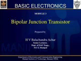
BASIC ELECTRONICS. MODULE 3 Bipolar Junction Transistor Prepared by H V Balachandra Achar Senior Lecturer, Dept. of E&C Engg., M I T, Manipal. Introduction to Bipolar Junction Transistor BJT Operation BJT Configurations Tutorials BJT Biasing Tutorials BJT Amplifier Tutorials.

E N D
BASIC ELECTRONICS MODULE 3 Bipolar Junction Transistor Prepared by H V Balachandra Achar Senior Lecturer, Dept. of E&C Engg., M I T, Manipal
Introduction to Bipolar Junction Transistor BJT Operation BJT Configurations Tutorials BJT Biasing Tutorials BJT Amplifier Tutorials Syllabus
“Electronic Devices and Circuit Theory” by Boylestad & Nashelsky, “Integrated Electronics” by Millman & Halkias, Reference Books
Solid state transistor was invented by a team of scientists at Bell laboratories during 1947-48 It brought an end to vacuum tube era Advantages of solid state transistor over vacuum devices: Smaller size, light weight No heating elements required Lower power consumption and operating voltages Low price Introduction
Introduction Figure showing relative sizes of transistor, IC and LED Figure showing different transistor packages
Bipolar Junction Transistor (BJT) is a sandwich consisting of three layers of two different types of semiconductor Two kinds of BJT sandwiches are: NPN and PNP Introduction
The three layers of BJT are called Emitter, Base and Collector Base is very thin compared to the other two layers Base is lightly doped. Emitter is heavily doped. Collector is moderately doped NPN – Emitter and Collector are made of N-type semiconductors; Base is P-type PNP – Emitter and Collector are P-type, Base is N-type Both types (NPN and PNP) are extensively used, either separately or in the same circuit Introduction
Transistor symbols: Introduction Note: Arrow direction from P to N (like diode)
BJT has two junctions – Emitter-Base (EB) Junction and Collector-Base (CB) Junction Analogous to two diodes connected back-to-back: EB diode and CB diode The device is called “bipolar junction transistor” because current is due to motion of two types of charge carriers – free electrons & holes Introduction
Operation of NPN transistor is discussed here; operation of PNP is similar with roles of free electrons and holes interchanged For normal operation (amplifier application) EB junction should be forward biased CB junction should be reverse biased Depletion width at EB junction is narrow (forward biased) Depletion width at CB junction is wide (reverse biased) Transistor Operation
Transistor Operation Un-biased transistor showing barriers at the junctions
Transistor Operation C-B junction is reverse biased – increased barrier height
Transistor Operation E-B junction is forward biased – aids charge flow
Transistor Operation Electron-hole combination – leads to small base current
When EB junction is forward biased, free electrons from emitter region drift towards base region Some free electrons combine with holes in the base to form small base current Inside the base region (p-type), free electrons are minority carriers. So most of the free electrons are swept away into the collector region due to reverse biased CB junction Transistor Operation
Three currents can be identified in BJT Emitter current This is due to flow of free electrons from emitter to base Results in current from base to emitter Base current This is due to recombination of free electrons and holes in the base region Small in magnitude (usually in micro amperes) Collector current Has two current components: One is due to injected free electrons flowing from base to collector Another is due to thermally generated minority carriers Transistor Operation
Note the current directions in NPN and PNP transistors For both varieties: ---(1) C IC C IC IB IB B B IE IE E E NPN PNP Transistor Operation
As noted earlier, collector current has two components: One due to injected charge carriers from emitter Another due to thermally generated minority carriers Both results in current in the same direction. Hence --- (2) αdc is the fraction of charge carriers emitted from emitter, that enter into the collector region ICBO is the reverse saturation current in CB diode --- (3) Transistor Operation
As approximation, we can neglect ICBO compared to IE and IC Hence approximate equations are: Like the reverse saturation current of ordinary diode, ICBO also doubles for every 10o rise in temperature. So ICBO cannot be neglected at higher temperatures The parameter αdc is called common-base dc current gain Value of αdc is around 0.99 Transistor Operation
We have Substituting for IE, we get Transistor Operation --- (4) Where and
Equations (2) and (4) are two alternate forms of BJT current equation Since value of αdc is around 0.99, ICEO >> ICBO However, ICEOis still very small compared to IC Hence approximation of (4) gives: or Parameter βdc is called common emitter dc current gain Values of αdc and βdc vary from transistor to transistor. Both αdc and βdc are sensitive to temperature changes Transistor Operation
A BJT has alpha (dc) 0.998 and collector-to-base reverse sat current 1μA. If emitter current is 5mA, calculate the collector and base currents. (Ans: 4.99 mA, 10 μA) An npn transistor has collector current 4mA and base current 10 μA. Calculate the alpha and beta values of the transistor, neglecting the reverse sat current ICBO (Ans: 0.9975, 400) In a transistor, 99% of the carriers injected into the base cross over to the collector region. If collector current is 4mA and collector leakage current is 6 μA, Calculate emitter and base currents (Ans: 4.034 mA, 34 μA) Problems
BJT has three terminals For two-port applications, one of the BJT terminals needs to be made common between input and output Accordingly three configurations exist: Common Base (CB) configuration Common Emitter (CE) configuration Common Collector (CC) configuration (The last one is not discussed in this course) 2-port device Input Output Transistor Configurations
Transistor Configurations • Common Base configuration (Resistors are not shown here for simplicity) • Base is common between input and output • Input voltage: VEB Input current: IE • Output voltage: VCB Output current: IC
Transistor Configurations • CB Input characteristics • A plot of IE versus VEB for various values of VCB • It is similar to forward biased diode characteristics • As VCB is increased, IE increases only slightly • Note that second letter in the suffix is B (for base)
Transistor Configurations Input resistance ri Voltage amplification factor AV Both can be determined from the CB input characteristics
CB Output characteristics A plot of IC versus VCB for various values of IE Three regions are identified: Active, Cutoff, Saturation Active region: E-B junction forward biased C-B junction reverse biased IC is positive, VCB is positive IC increases with IE For given IE, IC is almost constant; increases only slightly with increase in VCB. This is due to base-width modulation (Early effect) Transistor Configurations
Transistor Configurations CB Output characteristics 1.Active Region 2.Saturation Region 3.Cut off Region
Base Width modulation As the reverse bias voltage VCB is increased, the depletion region width at the C-B junction increases. Part of this depletion region lies in the base layer. So, effective base width decreases. Hence number of electron-hole combination at the base decreases. So base current reduces and collector current increases. Note that IE = IC + IB Transistor Configurations
When IE = 0, IC = ICBO ICBO is collector to base current with emitter open Below this line we have cut-off region Here both junctions are reverse biased Region to the left of y-axis (VCB negative) is saturation region Here both junctions are forward biased IC decreases exponentially, and eventually changes direction Transistor Configurations
Transistor Configurations Output resistance ro • Both can be measured from output characteristics Current amplification factor AIorαac
Transistor Configurations • Common Emitter configuration (Resistors are omitted for simplicity) • Emitter is common between input and output • Input voltage: VBE Input current: IB • Output voltage: VCE Output current: IC
Transistor Configurations CE input characteristics • Plot of IB versus VBE for various values of VCE • Similar to diode characteristics • As VCE is increased, IB decreases only slightly • This is due to base-width modulation • Note that second suffix is E (for emitter)
CE output characteristics A plot of IC versus VCE for various values of IB Three regions identified: Active, Cut-off, Saturation Active region: Linear region in the output characteristics E-B junction forward biased C-B junction reverse biased IC increases with IB For given IB, IC increases slightly with increase in VCE; this is due to base-width modulation (Early effect) Transistor Configurations
Transistor Configurations CE output characteristics
Note that VCE = VCB + VBE So if VCE is increased, effectively VCB also increases For saturation to take place, C-B junction should be forward biased. This happens when VCE is approximately 0.3 V (or less) for Si Note that when VCE= 0.3V, and VBE= 0.6 V, VCB= – 0.3V (a forward bias of 0.3 V) So region to the left of the vertical line VCE=VCE(sat)=0.3V (for silicon) is considered as saturation region Region below IB=0 line (or IC=ICEO) is cut-off region Transistor Configurations
Transistor Configurations • ICEO is much larger than ICBO because of the relation: Note that value of αdc is around 0.99 The values of αdc & αac, and βdc & βac are almost the same. Hence the subscripts can be omitted for simplicity
Input resistance ri Transistor Configurations Output resistance ro Voltage gain AV Current gain AIorβac All these parameters can be determined from CE characteristics
Transistor Configurations • Experimental setup for determining CE characteristics:
A Ge transistor with β = 100 has collector-to-base leakage current of 5 µA. If the transistor is connected in common-emitter operation, find the collector current for base current (a) 0 (b) 40 µA. Sol: Given that ICBO = 5µA, and β = 100 We know that When IB = 0, IC= ICEO = (β+1)ICBO = 505 µA When IB = 40 µA, IC= βIB + ICEO = (100 × 40 × 10–6) + (505 × 10–6) = 4.505 mA Tutorials
2. A Ge Transistor has collector current of 51 mA when the base current is 0.4 mA. If β = 125, then what is its collector cutoff current ICEO? (Ans: 1 mA) 3. In a transistor circuit, when the base current is increased from 0.32 mA to 0.48 mA, the emitter current increases from 15 mA to 20 mA. Find αacand βac values. (Ans: 0.968, 30.25) 4. A transistor with α = 0.98 and ICBO = 5 µA has IB = 100 µA. Find ICand IE. (Ans: 5.15 mA, 5.25 mA) Tutorials
What is meant by biasing the transistor? Applying external dc voltages to ensure that transistor operates in the desired region Which is the desired region? For amplifier application, transistor should operate in active region For switch application, it should operate in cut-off and sat. What is meant by quiescent point (Q-point)? The point we get by plotting the dc values of IC , IB and VCE (when ac input is zero) on the transistor characteristics Transistor Biasing
Transistor Biasing • Transistor characteristics showing Q-point • Q-point is in the middle of active region. • This is called “Class-A” operation. (Other classes are discussed later)
Transistor Biasing • Types of biasing: • Fixed bias and Self bias • Fixed bias: • The value of IB is “fixed” by choosing proper value for RB • Equations to consider are:
Pros and Cons of Fixed bias: Pros: 1) Simple circuit 2) Uses very few resistors Cons: Q-point is unstable 1) If temperature increases, then βincreases, and hence ICQ and VCEQvary (effectively Q-point shifts) 2) If the transistor is replaced with another transistor having different βvalue, then also Q-point shifts Transistor Biasing
Transistor Biasing • Load Line • We have: • This is an equation of straight line with points VCC/RC and VCC lying on y-axis and x-axis respectively • This line is called “Load line” because it depends on resistor RC considered as “Load” and VCC • Intersection of load line and transistor characteristic curve is the Q-point or operating point • This point is the common solution for characteristics and load line equation
Transistor Biasing Variation in load line with circuit parameters VCC, RC and RB
Transistor Biasing • Voltage divider bias or Self bias • Resistor RE connected between emitter and ground • Voltage-divider resistors R1 & R2 replace RB • Circuit can be analyzed in two methods: • Exact method (using Thevenin’s theorem) • Approximation method (neglecting base current)