Download
1 / 23
230 likes | 450 Views
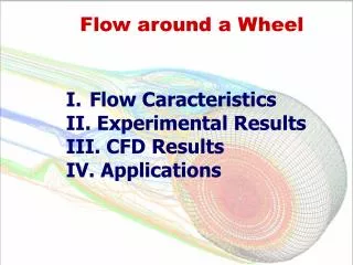
Investigation of the air boundary layer around a rotating grinding wheel. Hui Wu. Advanced Manufacturing Technology Research Laboratory General Engineering Research Institute Liverpool John Moores University. 07 November 2008. Content of presentation. Introduction and review

E N D
Investigation of the air boundary layer around a rotating grinding wheel Hui Wu Advanced Manufacturing Technology Research Laboratory General Engineering Research Institute Liverpool John Moores University 07 November 2008
Content of presentation • Introduction and review • Experimental arrangement and method • Experimental results and discussion • Further results from CFD simulation • Conclusions
Introduction and review Problems in grinding process: • High specific energy, which is converted to heat in the grinding zone • High temperature causes thermal damage to the workpiece - burning, phase transformations - softening surface layer with possible re-hardening - unfavourable residual tensile stresses - cracks, and reduced fatigue strength - accelerate wheel wear • Contribute to inaccuracies and distortions in the final product
Introduction and review Problems in grinding process: Grinding fluid is applied in order to limit the high temperatures and thermal damage and wheel wear. Role of grinding fluid: lubrication, bulk cooling and transport of debris.
Introduction and review Problems in fluid delivery in grinding: • Grinding fluid must be delivered to the grinding zone in sufficient volume. (for effective lubricating and cooling) • Air boundary layer develops around the periphery of the wheel surface in grinding, which may prevent the fluid reaching the wheel surface. • Two main methods of grinding fluid delivery: low pressure nozzle (flood) high pressure nozzle (jet) • Fluid delivery at high pressure (jet) leads to increased friction and wastage of power. • Fluid delivery via a low-pressure system may be insufficient to penetrate this air boundary layer, especially in high-speed grinding.
Introduction and review Interest on air boundary layer investigation: The air boundary layer flow has sufficient energy to prevent the fluid reaching the wheel surface and the grinding contact zone. This has aroused interest that has led to the studies of the air boundary layer flow around the rotating grinding wheels. The air velocity distribution has been measured by some researchers. Cutting fluid backing up due to boundary layer effects S. Ebbrell etal (1999)
Introduction and review Problems in previous measurement of air boundary layer: • Most of the previous measurements were intrusive measurement method (not sensitive enough to measure the low velocity air flow) • Most previous researchers only measured the tangential component velocity of the air boundary layer (one component velocity) • Different measurement methods and experimental parameters led to conflicting results • Therefore, a comprehensive understanding of the air boundary layer flow has not been obtained
Measurement area wheel Introduction and review Review of previous measurements: V. N. Serov (1965): air velocity changes along the wheel width reaching a minimum value in the middle section. Method: unknown V. Radhakrishnan (1977): Similar to Serov’s results Method: Pitot tube and hot-wire
Measurement area wheel Introduction and review Review of previous measurement: J. Shibata (1982): Two peaks around the sides of the wheel close to wheel surface, but tend to shift to the center of the wheel width with the distance to the wheel surface Method: Hot-wire anemometer Sven Alenius (1996): Air central peak along the wheel width Method: Pitot tub
Experimental arrangement and method LDA measurement: • Laser Doppler Anemometry (LDA) represents a most effective tool in the fluid velocity measurements. • Advantages of the LDA: non-intrusive measurement with high temporal and spatial resolution • Ideal measurement technique for the investigation of air flow velocity. (c) PC (a ) Laser system generator (b) Burst Spectrum Analyzer (BSA) LDA measurement system
Experimental arrangement and method Experimental arrangement: • Grinder: Abwood Series 5020 surface grinding machine • LDA: Argon+-ion LDA system (two-component dual-beam LDA , back-scatter mode) • Seeding particle: Smoker generator
Experimental arrangement and method Experimental arrangement: Wheel Parameters: • Material: Alumina • Diameter: 182.5mm • Width: 25mm • Surface roughness: Rt=2mm Schema of the configuration
Experimental arrangement and method Experimental Method: Lattice of measurement points Measurement coordinate system and the measurement area
Experimental arrangement and method Experimental works presented: Air tangential velocity contour map with different wheel speed (Vs) Air radial velocity contour map with different wheel speed Effect of the wheel speed on air velocity Effect of the wheel roughness on air velocity Tangential and radial velocity turbulent value map
Experimental results Air tangential velocity contour maps: (Vs = 20m/s) (Vs = 30m/s) (Vs = 40m/s) • The air tangential velocity has its highest value close to the wheel surface. • The highest tangential air velocity is always in the wheel middle section along the wheel width. • Close to the wheel edges, the gradient of Vt is high.
Experimental results Air radial velocity contour maps: (Vs = 20m/s) (Vs = 30m/s) (Vs = 40m/s) • In one wheel speed, the maximum radial velocity is the distance of about 25mm to the wheel surface in the wheel middle section • the radial velocity is increasing with increasing wheel speed
Wheel Vt distribution with distance to wheel surface Measurement line Experimental results Effect of the wheel speed on air velocity: Vt in one point with increasing wheel speed • Tangential velocity exponentially decreases with distance from the wheel surface. • Tangential velocity is linear proportionally with the wheel speed in one point.
Experimental results Effect of the wheel roughness on air velocity: Wheel Measurement line Air Vt VS wheel surface roughness The wheel surface roughness is bigger, the air flow velocity is higher.
Experimental results Tangential and radial velocity turbulent value map: Air velocity turbulent value is the percentage of the RMS velocity value divided by the mean velocity value. Vt and Vr Percent Turbulent distribution (Vs=30m/s)
CFD Simulation: Tangential and radial velocity turbulent value map: Vr simulation contour (Vs = 30m/s) Vt simulation contour (Vs = 30m/s)
CFD Simulation: Air flow vector (Vs = 30m/s) Simulation result Experimental result
Conclusions • The Laser Doppler Anemometry (LDA) was successfully employed to investigate the grinding air boundary layer around the rotating grinding wheel • The velocity distributions of the air boundary layer flow were fully observed and investigated. • The results of the experiments and simulations clarify the full understanding of the air boundary layer compared to previous research. • These outcomes will help users to optimize the fluid delivery design when thinking about the effect of the air boundary layer.