Display Modes
Display Modes. Display Mode. A mode M mode B mode. A mode. First form of echo display. Echoes displayed as vertical deflection. Horizontal axis represents distance or depth. The vertical axis represents the amplitude of the echoes. A mode. The horizontal position of the A-mode on the

Display Modes
E N D
Presentation Transcript
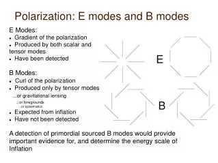
Display Mode • A mode • M mode • B mode
A mode • First form of echo display. • Echoes displayed as vertical deflection. • Horizontal axis represents distance or depth. • The vertical axis represents the amplitude of the echoes.
A mode The horizontal position of the A-mode on the CRT display depends on the transducer- reflector time relationship. • The electronic beam is swept horizontally by the horizontal sweep generator at a speed of 1540 m/s from left to right. • The CRT electron beam is synchronized to start the sweeping action with the application of the transmit pulse voltage.
A-mode The vertical position of the trace is determined by the voltage signal amplitude from the video amplifier. The height of the vertical deflection depends on the amplitude of the echoes and receiver function such as the gain and TGC settings.
A-mode Amplitude (y-axes) Distance (x-axis)
B-mode B-mode means Brightness mode. • Echoes are displayed brightened dots. • The strength of the echoes determines the brightness. • The position of the B-mode dot on the screen represents the reflector distance and is determine by the transducer-reflector time relationship.
M-MODE • B mode echoes form an interface that changes position will be seen as echoes moving towards and away from the transducer. • If a trace line is place on this interface and the resulting trace is made to drift across the face of a CRT screen a motion pattern is obtained.
M-MODE • The resulting display shows motion of a reflector over distance and time – a distance time graph. • The change in distance (dy) over a period of time dt is represented by the slope of the reflector line of motion. • dy/dt = slope = velocity
M-MODE • If this motion pattern is obtained on moving cardiac structures then the resulting images constitute M-mode echocardiography. • M-mode echocardiography is use to evaluate the morphology, movement and velocity of cardiac valves and walls.
M-mode Tracing Distance Time
M-mode Evaluation • Amplitude • Velocity • Morphology
Amplitude Measurement Y2 Amplitude = Y2 –Y1 Y1
Slope Measurement Y2 dy = Y2 –Y1 Y1 Slope = dy/dt T1 T2 dt = T2 – T1
Real Time Scanner RT describe an ultrasound system that • Acquires • Processes • Displays Images without storing the echo data.
Frame Rate • Each sweep of the ultrasound beam produces a frame. • The frame is made up of scan lines • Each can line is produce by a ultrasound pulse • The frame rate depends on the rate of pulse production (pulse repetition frequency) and the number of scan lines in that frame.
Frame Rate Frame Scan lines Frame rate = PRF/lines per frame
Frame Rate Increase Frame Rate by Increasing PRF • Decreasing image depth Decreasing # of lines per frame • Decrease frame width • Decrease Scan line density -
Frame Rate Frame Scan lines Frame rate = PRF/lines per frame
Increasing Frame RateDecreasing Image Depth Frame Scan lines Frame rate = PRF/lines per frame
Increasing Frame RateDecreasing Scan Line Density Frame Scan lines Frame rate = PRF/lines per frame
Increasing Frame RateDecreasing Frame Width Frame Scan lines Frame rate = PRF/lines per frame
Frame Rate Decrease Frame Rate by Decreasing PRF • Increasing image depth Increasing # of lines per frame • Increase frame width • Increase Scan line density • Increase # of pulses per scan line - Multiple focal zones - Color Doppler
Frame Rate Frame Scan lines Frame rate = PRF/lines per frame
Decreasing Frame RateIncrease Image Depth Frame Scan lines Frame rate = PRF/lines per frame
Decreasing Frame RateIncreasing Scan Line Density Frame Scan lines Frame rate = PRF/lines per frame
Decrease Frame RateMultiple Focal Zones Frame Focal Zones Frame rate = PRF/lines per frame
Decrease Frame RateColor Doppler Frame Scan lines Frame rate = PRF/lines per frame
Frame Rate The faster the moving reflector the higher the frame required in order to display continuous motion
Frame Rate • Frame rate – 15 and 60 f/s • Can be adjusted by the operator • Automatically adjusted as a function of depth and or field of view.
Temporal Resolution Temporal resolution is a measure of the ability to separate events in time. The frame rate determines the ability to capture motion accurately. The higher the frame rate the better the temporal resolution.
Temporal Resolution The following factors affect the frame rate and thus the temporal resolution. • Image depth • Wide field of view • Multiple transmit focal zones • Color Doppler • Scan line density
Beam Steering RT scanners sound beam is steered rapidly and repeatedly.
Beam Steering Steering Mechanism Mechanical Electronic Linear Switched Linear Phase Oscillating Mirror Rotating
Rotating Transducer Flexible Cable Rotation Point Crystal Membrane
Oscillating Transducer Oscillating membrane Annular array Coupling membrane
Array Transducer Linear array Phased array Annular array