Automobile Emission Control
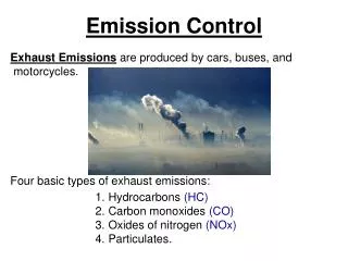
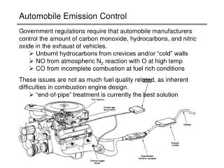
Automobile Emission Control. Government regulations require that automobile manufacturers control the amount of carbon monoxide, hydrocarbons, and nitric oxide in the exhaust of vehicles. Unburnt hydrocarbons from crevices and/or “cold” walls

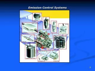
Automobile Emission Control
E N D
Presentation Transcript
Automobile Emission Control • Government regulations require that automobile manufacturers control the amount of carbon monoxide, hydrocarbons, and nitric oxide in the exhaust of vehicles. • Unburnt hydrocarbons from crevices and/or “cold” walls • NO from atmospheric N2 reaction with O at high temp • CO from incomplete combustion at fuel rich conditions • These issues are not as much fuel quality related, as inherent difficulties in combustion engine design. • “end-of-pipe” treatment is currently the best solution J.S. Parent
Exhaust Gas Composition • Spark-ignited gasoline engine emissions of CO, NO and hydrocarbons (expressed as hexane) as a function of intake air-to-fuel ratio in grams of air per gram of fuel. • HC and CO emissions decline with increasing O2 injection. • Conditions that maximize the flame temperature will generate high NO levels. • Need to consider fuel economy as well as pollution abatement. J.S. Parent
Automobile Emission Standards (U.S.) • Exhaust emission standards for automobiles and trucks were established in 1970 and amended in 1990. Below are shown the standards for automobiles. • Emission Standards (g/km) • Year Hydrocarbons CO NOx • Uncontrolled 6.56 52.2 2.6 • 1975 0.94 9.4 1.9 • 1980 0.25 4.4 1.2 • 1990 0.25 2.1 0.6 • 1995 0.19 2.1 0.2 • 2004 0.08 1.1 0.1 • Compliance is now required for 10 years or 160,000 km, with relaxed standards for the second 80,000 km of vehicle life. Note that testing is conducted throughout this mileage, and the vehicle must meet the standard at the end of the period. J.S. Parent
Emissions Testing • The 1975 Federal Test Procedure (FTP) is a driving cycle through Los Angeles over which total pollutant emissions are measured. • Cycle Length: 11.115 miles • Cycle Duration: 1877 sec plus 600-second pause • Bag I (cold start) 0-505 sec • Bag 2 505-1,370 sec • Hot soak (run idle) 600 sec • Bag 3 (hot start) 0-505 sec • Average Speed: 34.1 km/hr • Maximum Speed: 91.2 km/hr • Number of hills: 23 J.S. Parent
Example of an Emissions Test • CO and hydrocarbon tailpipe • emissions from a test vehicle • during a test cycle. Also shown • is the catalyst temperature and • speed during the cycle. • Catalyst mounted 1.2 m from • exhaust manifold. • As can be seen, the principal CO • and hydrocarbon emissions • occur catalyst warmup. Data for • NO production is not reported. • When hot, the catalyst is very • effective. In practice, one can expect • between 60 and 90% of the engine CO and hydrocarbon emissions, as measured over the whole test cycle, to be removed by the catalyst after 50,000 miles of use. J.S. Parent
The Start-up Problem • A poorly adjusted vehicle can fail • a modern emissions test within • the first 100 seconds of operation, • especially if the choke is needed • for starting. • In region I shown at right, the • catalyst is at too low a temperature • to be effective. The “light-off” temp • of today’s catalysts is 250 to 300C, • shown here as the end of region II • where kinetic control is observed. • Various technologies are being developed to deal with this problem • exhaust gas igniter in the exhaust line (Ford) • air-pumps to promote catalytic HC oxidation and light-off • electrically heated catalyst beds J.S. Parent
Catalytic Reactions for Emission Control • Up until about 1980, catalytic converters were used to control only CO and hydrocarbon emissions. The engine was run lean for performance reasons, and air was mixed with exhaust into the oxidizing converter. • Oxidation reactions: • CmHn + 2(m+n/4) O2 n/2 H2O + m CO2 • CO + 1/2 O2 CO2 • CO + H2O CO2 + H2 • Dispersed Pt and Pd in a 5:2 ratio on alumina was used for reasons of durability and activity (size of unit). Comparison of relative activities of precious and base metal catalysts Reactant 1% CO 0.1% C2H4 0.1% C2H6 Pd 500 100 1 Pt 100 12 1 Co203 80 0.6 0.05 Au 15 0.3 <0.2 MnO2 4.4 0.04 CuO 45 0.6 Fe203 0.4 0.006 Reaction in Oxidizing Atmosphere at 300C J.S. Parent
Three-Way Conversion (TWC) Catalysts • NOx emission standards created real design problems: • NOx reduction is most effective in the absence of O2 • CO and HC abatement requires O2 • To avoid a reducing reactor and an oxidizing reactor in series, we require both oxidation and reduction reactions in the same space. For this to occur, a catalyst must react all potential reducing agents (CO, H2 and hydrocarbons) with all oxidizing agents (O2 and NO). • TWC reactions at stoichiometric A/F mixtures: • CO + NO 1/2 N2 + CO2 • CmHn + 2(m+n/4) NO (m + n/4) N2 + n/2 H2O + m CO2 • H2 + NO 1/2 N2 + H2O • CO + H2O CO2 + H2 (water-gas shift r’n) • CmHn + m H2O m CO + (m + n/2) H2 (steam reforming) • Other NO-reduction reactions: • 2 NO + 5 H2 2 NH3 + 2 H2O • NO + hydrocarbons N2 + H2O + CO2 + CO + NH3 J.S. Parent
TWC Catalysts • The operating window for efficient TWC • catalyst operation is narrow and the fuel mixture must be carefully controlled. • Rhodium and Iridium are capable of catalyzing the reaction of CO, H2 or hydrocarbons selectively with NO as opposed to O2, which is important under lean conditions. Pt reduces NO to NH3, which is ineffective. • Oxidation in the presence of O2 is relatively simple, but in a rich condition Pt is found to catalyze CO and hydrocarbon oxidation through the water-gas shift reaction and steam reforming reaction, respectively. • North American TWC systems use approx 10:1 Pt to Rh, with about 0.05 troy oz/converter of Pt. J.S. Parent
Closed-Loop Fuel Metering System • TWC systems require the • air-to-fuel mixture charged • to the engine to be controlled • precisely if they are to • function effectively. • This is accomplished by • positioning an oxygen sensor • in the exhaust manifold to record • the discharge O2 content. Air flow to the engine is monitored as it responds to variations in throttle position and load. • Computer control regulates the fuel metered to the engine to control the reaction stoichiometry. • The TWC catalyst “sees” an exhaust composition that fluctuates between rich and lean, and must be capable of dealing with a range. J.S. Parent
TWC Catalyst Design: Monoliths • Design of the catalyst support is as important as fuel mixture control and catalytic chemistry. From the perspective of plug flow reactor design, key issues/design parameters are: • space velocities from 10,000 to 100,000 l/hr depending on engine size and mode of driving • minimal pressure drop for improved engine output • low thermal inertia for quick heat up • Materials design issues include: • stability at to temperatures up to 800C • ability to withstand rapid heating • surface area, metal dispersion and resistance to sintering • mechanical properties sufficient to last 160,000 km of use. • Most catalytic converters are constructed from ceramic monolithic supports of a magnesium aluminum silicate. J.S. Parent
TWC Catalyst Design: Monoliths • Monolithic honeycombs are used • in the place of pellets. The most • common cell structure used has • 62 cells/cm2 with a 0.152 mm • thick wall to give a bulk • density of 0.4 g/cm3. • The ceramic has a relatively • low surface area for catalysis, • and a “washcoat” in the form of an • aqueous suspension of alumina and • other components is applied and fixed by calination. • The washcoat provides a means of dispersing precious metals to a high degree, while reducing coalescence sintering and acting as a sink for poisons. The application procedures highly evolved and are proprietary. J.S. Parent