Download

1 / 22
340 likes | 1.13k Views
83. EVAPORATIVE EMISSION CONTROL SYSTEMS. Figure 83-1 A capless system from a Ford Flex does not use a replaceable cap; instead, it is spring-loaded closed.

E N D
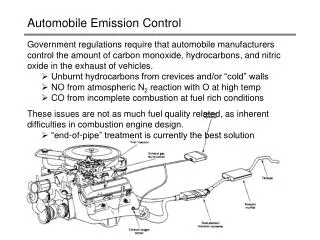
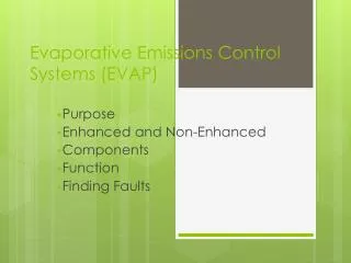
83 EVAPORATIVE EMISSION CONTROL SYSTEMS
Figure 83-1 A capless system from a Ford Flex does not use a replaceable cap; instead, it is spring-loaded closed.
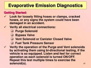
FREQUENTLY ASKED QUESTION: When Filling My Fuel Tank, Why Should I Stop When the Pump Clicks Off? Every fuel tank has an upper volume chamber that allows for expansion of the fuel when hot. The volume of the chamber is between 10% and 20% of the volume of the tank. For example, if a fuel tank had a capacity of 20 gallons, the expansion chamber volume would be from 2 to 4 gallons. A hose is attached at the top of the chamber and vented to the charcoal canister. If extra fuel is forced into this expansion volume, liquid gasoline can be drawn into the charcoal canister. This liquid fuel can saturate the canister and create an overly rich air-fuel mixture when the canister purge valve is opened during normal vehicle operation. This extra-rich air-fuel mixture can cause the vehicle to fail an exhaust emissions test, reduce fuel economy, and possibly damage the catalytic converter. To avoid problems, simply add fuel to the next dime’s worth after the nozzle clicks off. This will ensure that the tank is full yet not overfilled.
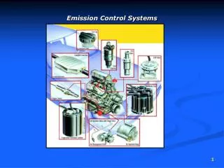
Figure 83-2 A charcoal canister can be located under the hood or underneath the vehicle.
Figure 83-3 The EVAP system includes all of the lines, hoses, and valves, plus the charcoal canister.
Figure 83-4 A typical EVAP system. Note that when the computer turns on the canister purge solenoid valve, manifold vacuum draws any stored vapors from the canister into the engine. Manifold vacuum also is applied to the pressure control valve. When this valve opens, fumes from the fuel tank are drawn into the charcoal canister and eventually into the engine. When the solenoid valve is turned off (or the engine stops and there is no manifold vacuum), the pressure control valve is spring-loaded shut to keep vapors inside the fuel tank from escaping to the atmosphere.
CHART 83–1 Pressure conversions. NOTE: 1 PSI = 28 in. H2O, 0.25 PSI = 7 in. H2O
Figure 83-5 An enhanced EVAP system is able to perform system and leak detection diagnosis.
Figure 83-6 A leak detection pump (LDP) used on some Chrysler and other vehicles to pressurize (slightly) the fuel system to check for leaks.
TECH TIP: Problems after Refueling? Check the Purge Valve The purge valve is normally closed and open only when the PCM is commanding the system to purge. If the purge solenoid were to become stuck in the open position, gasoline fumes would be allowed to flow directly from the gas tank to the intake manifold. When refueling, this would result in a lot of fumes being forced into the intake manifold and as a result cause a hard-to-start condition after refueling. This would also result in a rich exhaust and likely black exhaust when first starting the engine after refueling. While the purge solenoid is usually located under the hood of most vehicles and is less subject to rust and corrosion as with the vent valve, it can still fail.
Figure 83-7 A restricted fuel fill pipe shown on vehicle with the interior removed.
Figure 83-8 Some vehicles will display a message if an evaporative control system leak is detected that could be the result of a loose gas cap.
Figure 83-9 To test for a leak, this tester was set to the 0.020-inch hole and turned on. The ball rose in the scale on the left, and the red arrow was moved to that location. If when testing the system for leaks the ball rises higher than the arrow, then the leak is larger than 0.02 inch. If the ball does not rise to the level of the arrow, the leak is smaller than 0.020 inch.
Figure 83-10 This unit is applying smoke to the fuel tank through an adapter, and the leak was easily found to be the gas cap seal.
Figure 83-11 An emission tester that uses nitrogen to pressurize the fuel system.
Figure 83-12 The fuel tank pressure sensor (black unit with three wires) looks like a MAP sensor and is usually located on top of the fuel pump module (white unit).
Figure 83-13 A tank car was cleaned using steam, and then both the bottom drain and the top vent were closed. The next day, the tank had collapsed because of the air pressure difference when the inside cooled. The higher outside air pressure caused the tank to collapse.
TECH TIP: Always Tighten the Cap Correctly Many diagnostic trouble codes (DTCs) are set because the gas cap has not been properly installed. To be sure that a screw-type gas cap is properly sealed, tighten it until you hear three clicks. The clicking is a ratchet device, and the clicking does not harm the cap. Therefore, if a P0440 or similar DTC is set, check the cap. - SEE FIGURE 83–14 .
Figure 83-14 This Toyota cap warns that the check engine light will come on if not tightened until one click.
Figure 83-15 To easily check the fuel tank pressure sensor, remove the cap, and the sensor should read about 1.7 volts.
Figure 83-16 The fuel level must be above 15% and below 85% before the EVAP monitor will run on most vehicles.
TECH TIP: Keep the Fuel Tank Properly Filled Most evaporative system monitors will not run unless the fuel level is between 15% and 85%. In other words, if a driver always runs with close to an empty tank or always tries to keep the tank full, the EVAP monitor may not run. - SEE FIGURE 83–16 .