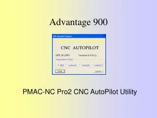
Advantage 900
Advantage 900. PMAC-NC Pro2 CNC AutoPilot Utility. PMAC-NC Pro2 CNC AutoPilot Utility. The CNC AutoPilot program is part of the PMAC-NC Pro2 installation. It is available from the NC folder. Verify the installation of the CNC AutoPilot. By default it is installed under:


Advantage 900
E N D
Presentation Transcript
Advantage 900 PMAC-NC Pro2 CNCAutoPilot Utility
PMAC-NC Pro2 CNC AutoPilot Utility • The CNC AutoPilot program is part of the PMAC-NC Pro2 installation. It is available from the NC folder. • Verify the installation of the CNC AutoPilot. By default it is installed under: C:\Program Files\Delta Tau\PMAC-NC Pro2 RunTime\NC Setup Or C:\Program Files\Delta Tau\PMAC-NC Pro2 Designer\NC Setup
PMAC-NC Pro2 CNC AutoPilot Utility • The CNC AutoPilot was developed to assist in setting up basic NC functionality, allowing the integrator to concentrate on custom machine software (e.g., tool logic development, ESTOP logic development, etc.). • This program works as a Wizard to generate the CNC project files, configuration of the axis motor relations, machining parameters, and the standard PLC’s for the Advantage 900, 810 and 600 hardware. • CNC AutoPilot also creates a modular file template, the “Project Workspace” used by PEWIN32Pro. This helps in documentation and control of the machine software. • This program sets up the default NC registry entries for MILL or LATHE applications. • CNC AutoPilot is for setting the NC related parameters, not PMAC setup (motor phasing and servo tuning). The appropriate PMAC Setup program is used for this.
PMAC-NC Pro2 CNC AutoPilot Utility • Select the CNC AutoPilot app-lication from NCUI folder or the Start Menu. At the start of the application, the introduction window will be displayed • This dialog box will display the Software Release date (APR 28 2005 or greater), version number and build number (4.0 or greater). This is important for any technical support issues. The default setting for Application Type is MILL. Select the type of application de-pending upon your machine type.
PMAC-NC Pro2 CNC AutoPilot Utility • Click Start to continue. The PMAC Devices dialog box will be displayed. Select the appropriate device from the list. Click the Properties button to set up dual port RAM communication (necessary for NC software). The following dialogs will be the same for USB, Ethernet and PCI.
PMAC-NC Pro2 CNC AutoPilot Utility • Select the “DPR RT Buffers” Button first. Mark the check box for “DPRAM Real-Time Update“ and enter an appropriate update rate (the default of 20 servo cycles should be OK for most users). Then select the motors for the application. For example, in a typical MILL application there are 4 axes, X, Y, Z, and spindle i.e. 4 motors these may correspond to motors #1, #2, #3 and #4.
PMAC-NC Pro2 CNC AutoPilot Utility • Next select the “DPR BG Buffers” Button. Mark the check box for “DPRAM BackGround Update“ and enter an appropriate update rate (the default of 20 servo cycles should be OK for most users). This will determine the minimum rate for display update. Also select the number of coordinate systems the application requires (usually one). Click the OK button to go back to the PMAC Device dialog box.
PMAC-NC Pro2 CNC AutoPilot Utility • Press OK to exit from the “PMACDevices“ dialog box. The “PcommServer” dialog should appear with the message “The PMAC was successfully detected”, select “OK”.
PMAC-NC Pro2 CNC AutoPilot Utility • At this point, the AutoPilot program will check the application type with (Mill or LATHE A, B or C) and will ask for confirmation to set the NC user interface registry. This pop-up message will not be displayed on a fresh installation If you to run AutoPilot again, then this pop-up message will be displayed.
PMAC-NC Pro2 CNC AutoPilot Utility By clicking the “YES“ button, all previous NC settings will be lost. Clicking the “No“ button presents the first AutoPilot main setup screen. There are four tabs. • Axis – Motor – Assigns axis to motor • Std PLC – Select and configure standard NC PLC • Machine Setup – Set up machine parameters like Jog speed, Rapid(G0) speed etc. • NCUI Registry – Set up default.
PMAC-NC Pro2 CNC AutoPilot Utility Axis-Motor tab Axis-Motor Definitions: The first step will be assigning Motors to the axis. Select the Axis-Motortab. There are three columns under Axis-Motor Definitions: • Axis (Name) • Mtr No. • Pulses Per Unit. Axis Names are fixed (X, Y, Z etc.), Mtr No. and Pulses Per Unit entries are user assigned values.
PMAC-NC Pro2 CNC AutoPilot Utility Mtr No. • Any motor can be assigned to any axis. For example, motor 2 can be assigned to axis X or 3 to axis Y, etc. The motor number cannot be duplicated, i.e., assignment of motor 1 to axis X and Y will result in an Invalid Motor Number error. • The range for Motor Number is 1 to 8.
PMAC-NC Pro2 CNC AutoPilot Utility Pulses Per Unit • This is the encoder counts per unit. If the machine unit is inch, then it is the number of encoder counts per inch. To calculate this value, use this formula: PPU = Decode Control * Encoder Lines * Screw Pitch * Unit conversion factor • Decode Control = Turbo PMAC I7mn0 parameter resultant decode multiplier value (x1, x2, or x4). Default is 4. • Encoder Lines = The number of lines specified by the Encoder manufacturer used for the feedback. Units are lines/rev. • Screw Pitch is specified rev/pitch length the units are usually revs/mm. • Unit conversion factor is the conversion of pitch length units to machine units. For a machine in inches this is usually mm/inch.
PMAC-NC Pro2 CNC AutoPilot Utility Pulses Per Unit Example: For standard 5mm-pitch ballscrew and 8192 line encoders, the pulses per unit value is: Pulses Per Unit = 4 cts/Line * 8192 lines/rev * rev/5mm *25.4 mm/inch = 166461.48 pulses per inch. Where 4 cts /line is decode control I7mn0 variable of PMAC
PMAC-NC Pro2 CNC AutoPilot Utility Reset All • Click this button to set all definitions to 0 (zero). Zero indicates that the axis is not connected, this function clears the axis motor definitions quickly.
PMAC-NC Pro2 CNC AutoPilot Utility Position Units and Display Format • Position Units This defines the position units of the machine in either English or Metric (inches or milimeters). This setting is for the complete machine, not for individual motors. The first time the program is started, this value defaults to English (Inch), and English (Inch) is checked on the window. Select Metric (mm) and the program will start in Metric thereafter until switched back to English. • Display Format This defines the display format for different position units. This display format is used by NCUI 32 to display the axis position. The convention of the format is {total number of digits}.{digits after the decimal point}. Default format is 9.4 which mean total width is nine digits with four digits after the decimal point.
PMAC-NC Pro2 CNC AutoPilot Utility Std PLCtab Use the Std PLC function to configure, create, and download PLCs to PMAC and start the basic function of the NC. The basic functionality includes: • Mode selection (including Home Mode) • Axis selection • Jog • Speed selection • Hand-wheel operation • All function keys from the Control panel (single step, optional stop, block del, etc.)
PMAC-NC Pro2 CNC AutoPilot Utility Machine Name and PLC Path Machine Name • Enter a machine name up to 15 characters in the Machine Name field. This name is used for generating the .CFG file as well as for creating the directory. The default machine name is Adv 600, which is one of Delta Tau’s available control panels. .For example, if the machine is MyMachine, then CNCAutoPilot will create the directory MyMachine under C:\Program Files\Delta Tau\. All of the PLCs, headers, etc. files are stored in this folder. PLC Path • The PLC Path field indicates where the PLC files are stored. The standard base path C:\Program Files\Delta Tau . The \<Machine Name> will be appended to base path to create folder for storing PLC. The Browse button is used to set PLC base path. As soon as a machine name is entered, the PLC path is updated automatically.
PMAC-NC Pro2 CNC AutoPilot Utility Cntl Panel Function • In the Cntl Panel group of fields, enter the values to create the Control Panel PLC. • PMAC-NC Pro2 supports different types of Control Panels. Currently this software supports Adv 600, Adv 810, Adv 900 and Software Panel. For details of these control panels see the hardware reference documents. The Control Panel PLC outputs changes according to the selection of the control panel. Select the appropriate panel. By default, Adv 600 control panel is selected. • The Software Control Panel is selected when NC4.x will be running without a hardware control panel. • The Control Panel PLCs support NC4.x and NC5.x software. These control panel PLCs will not work with older NC software such as NC2.36 or NC3.x. • To support old NC software, use the Autopilot that came with the installation of the old NC software
PMAC-NC Pro2 CNC AutoPilot Utility Adv. Settings • If the Adv. Settings function is clicked, the window shown below displays. Advance Settings is useful for ADV600 style control panel and ACC34 style PMAC I/O boards. No. of I/O Cards • This box is for adding I/O cards. Default control panel PLC reads and writes one I/O card. When the control panel type is Adv 810, then these settings are not available. For Adv 810, use I/O M-Variables defined in the IO810.H file. The file can be found at C:\Program Files\Delta Tau Shared\IO810.h. This file is already included in the .CFG file output of Auto Pilot.
PMAC-NC Pro2 CNC AutoPilot Utility Override • Enter the values for the machine override parameters in this group of fields. ADV 810 and ADV900 control panels supports only ANALOG type overrides. % Spindle Override • Enter the values to set the Spindle Override percentages in this group of fields. The value in the % Speed Min field sets the minimum percentage spindle override and the value in the Speed Max field sets the maximum percentage spindle override. • The Digital and Analog options set the type of switch used for setting spindle override. • Range: Default 50 to 110 • Allowed 0 to 200 % Feedrate Override • This group of fields is used to set the feedrate override percentages. The value in the % Feed Min field sets the minimum percentage feedrate override and the value in the % Feed Max field sets the maximum percentage feedrate override. • The Digital and Analog options set the type of switch used for setting spindle override. • Range: Default 0 to 150 • Allowed 0 to 200
PMAC-NC Pro2 CNC AutoPilot Utility Home • Enter the value for the Home PLC in this group of fields. When Command is selected, the #{motor number}HM commands are issued through the Control Panel PLC. If selected, this button resets the Enable option. • When PLC is selected, the HOME commands are issued through the HOME PLC. This is set automatically if Enable is checked. • Currently, Home using the motion program feature is not available.
PMAC-NC Pro2 CNC AutoPilot Utility Handle • Enter the value for the Handle PLC in this group of fields. The value in the Max field sets the limit for the maximum handwheel increment per one revolution. By default, this increment is one unit. • The value in the Min field sets the minimum handwheel increment per division. • Default settings are: Hand Wheel Revs Speed Selection Position Increment 1 High (Max) 1 unit 1 Medium 0.1 unit 1 Low (Min) 0.01 unit • In this group, Max is set to 0.01 by default. A typical pulse generator has 100 divisions. Thus in High setting, the motor will move 0.01 *100 = 1 Unit.
PMAC-NC Pro2 CNC AutoPilot Utility Spindle • Enable the Spindle PLC in this group of fields. • Type: This parameter allows selection of the spindle type as Close Loop or Open Loop. The Close Loop spindle requires a feedback to PMAC; Open Loop does not (the spindle drive may still require feedback). • Max RPM: This parameter defines the maximum spindle RPM. The Spindle PLC uses this input to set the proper RPM. The program will not accept an RPM command greater than the value in the Max RPM field; it will clamp it to Max RPM.
PMAC-NC Pro2 CNC AutoPilot Utility PMAC Type • The program detects the type of the PMAC automatically and displays it here. Enable PLC • If Enable PLC is checked, then all of the generated PLCs are enabled by issuing “ENABLE PLC” command to PMAC after download. Save PLC • If Save PLC is checked, then the “SAVE” command is issued to PMAC after download. This saves all of the PLCs and I-Variables in the PMAC memory.
PMAC-NC Pro2 CNC AutoPilot Utility Machine Setup tab • Enter the values of all the machine related settings for NC, such as speed, following error, etc., in this group of fields. • The menu window is self-explanatory. The “AxisName” is displayed only if axes are assigned to the motor as displayed on the “AxisMotor” tab.
PMAC-NC Pro2 CNC AutoPilot Utility Jog Speed • This sets the maximum axis jog speed in user-selected units. The speed setting can be different for different motors. Rapid Speed • This sets the maximum axis rapid speed (G0 speed in NC terms) in user-selected units. This setting can be different for different motors. Positive S/W Limit • This sets the positive software limit in user-selected units. This setting can be different for each motor. Negative S/W Limit • This sets the negative software limit in user-selected units. This setting can be different for each motor.
PMAC-NC Pro2 CNC AutoPilot Utility Home Offset • This sets the distance in user-selected units to move after a “HOME” completes. This is a signed quantity. This setting can be different for each motor. Home Speed (and direction) • This sets the maximum machine home speed in user-selected units. This setting can be different for each motor. Speed can be positive or negative. Positive Limit Switch Negative Limit Switch Home Switch • This group of buttons per axis sets the basic condition for homing. For example, if Positive Limit Switch is selected, then homing will be done on the rising edge of the positive limit switch and the rising edge of C channel. This is the same for the other two switches. This setting can be different for each motor. Home on C Channel • Home on C Channel is used if the homing is to be done on the rising edge of C channel only. Only one type of condition is selected (Rising Edge).This setting can be different for each motor.
PMAC-NC Pro2 CNC AutoPilot Utility CS Setup • This group of fields contains the settings related to the NC coordinate system. Feed Rate • This sets the maximum axis feed rate in user-selected units. This setting is for all machine axes. This is G1, G2, G3 speed, in NC terms. Following Error • This sets the maximum following error in user-selected units. This setting is for all machine axes. In Position Band • This sets the In Position band in user-selected units. This setting is for all machine axes. LookAhead ON • This option is checked if the PMAC type is a Turbo. This sets the basic starting parameters for the look ahead mode for the NC. These settings depend upon the PMAC CPU frequency. The following I-Variables will be set for NC Coordinate System 1: • • I5113 = Move segmentation time in ms • • I5187 = Acceleration time in ms • • I5120 = Number of segments • For details on these parameters, refer to the PMAC Turbo User Manual.
PMAC-NC Pro2 CNC AutoPilot Utility Update • This option updates the Windows registry values used by the NC. Registry values must be updated after the configuration of axes is complete for the NC to reflect the setup configuration. Update will work only if the NC application is not running. In addition, registry values will not be updated if the registry key for that parameter is not present. In this case an error will be displayed. Build • When selected, this function generates the PLCs that are marked enable. All the PLCs are stored in the selected <PLCPATH>. • The next step is to download these PLCs manually, using PEWIN Executive software. Use the {MachineName}.CFG file for the download. Build and Download • This function generates the PLCs that are marked enable. All the PLCs are stored in selected <PLCPATH>. This downloads the {MachineName}.CFG file to PMAC automatically. If selecting ENABLEPLC and SAVEPLC, it issues the appropriate commands to PMAC.
PMAC-NC Pro2 CNC AutoPilot Utility Configuring the “NCUI Registry” tab.
PMAC-NC Pro2 CNC AutoPilot Utility File Management • NC Events Log File: This sets the path for storing NC events log. • NC Program to Load: This stores the NC file with path to be loaded in the NC interface on start-up of the application. • NC Program Folder: This sets the default NC file path. PMAC-NC will use this path as the default to open machine files.(“.NC”) . • NC Error File: This sets the path for storing the Errors data file. PMAC-NC will use this file to show user errors. • NC Variable File: This sets the path for storing the Parametric variables data file.
PMAC-NC Pro2 CNC AutoPilot Utility NC Buffers • Lookahead Buffer: This defines the number segments stored in the lookahead buffer. • Rotary Buffer: This defines the size of the rotary buffer used by NC program • Synchronous M Buffer: This defines the size of the Stack to hold synchronous M-variables. • The following commands for the coordinate system will be issued to PMAC: DEFINE ROTARY{Rotary Buffer} DEFINE LOOKAHEAD{Lookahead Buffer},{Synchronous M Buffer} • For details on these parameters, refer to the Turbo PMAC Users and Software Reference Manual
PMAC-NC Pro2 CNC AutoPilot Utility Miscellaneous User_Position_Reporting: If this check box is selected, then Autopilot will generate the default Position Reporting PLC. Users can alter this PLC and write their own calculation for position display. This is useful for displaying positions when inverse kinematics is used or for position displays using non conventional feedback devices. The feature will only work for Turbo PMAC Firmware V1.942 and above. WirelessPendentOn: If this check box is selected, then Autopilot will update the NC registry which will allow to use WIRELESS PENDENT with ADV900 Control panel. Velocity Scale X, Velocity Scale Y, Velocity Scale Z: These values are used as scale factor in Feed Rate calculation. HMI NC uses these values to display Feed Rate. Typically used when Dual feedback is used. The default is 1.
PMAC-NC Pro2 CNC AutoPilot Utility Tool This will allow the user to configure the Tool page columns in the NC as Geometry, Wear etc. The Maximum number of tools is 99. A number entry more than 99 will reset this field back to the default of 50 tools.
PMAC-NC Pro2 CNC AutoPilot Utility This section will give an example of the CNC AutoPilot Program. Refer to the different screen pictures which show the input for generating the standard PLCs for Adv 900 CNC control. On completion of these steps, the Build or Build & Download options can be clicked. If Build & Download is selected, make sure to check the ENABLE PLC and SAVE PLC option. Step 1: Run NC_Setup.EXE and select MILL option. Step 2: Set the Axis- Motor definition as shown in the next slide Step 3: Set machine Name for this example set it as MyMachine. Select ADV900 as control panel. Step 4: Set all the machine parameters (Jog Speed, Homing condition, following error etc.). Step 5: Set the NC default File path and Buffer sizes. Step 6: Check ENABLE PLC and SAVE PLC check boxes and click Build & Download. This will generate the PLC code and download it to PMAC. The PLCs are generated in a folder specified by PLC Path in Std PLC tab.
PMAC-NC Pro2 CNC AutoPilot Utility Axis - Motor definitions, Position Units and Display Format
PMAC-NC Pro2 CNC AutoPilot Utility • The ADV900 type control panel is selected. • Control Panel, Override, Handle and spindle close loop PLC are selected. • PMAC Type is UMAC. • Home command is issued from Control panel PLC. • Override controls are type Analog. • Initialize PLC is not selected so all the initialize part is done in Control panel plc.
PMAC-NC Pro2 CNC AutoPilot Utility • The maximum Feed Rate, Following Error, and In Position band settings are coordinate system-specific and are in USER UNITS. (inches as specified in previous screen). • Lookahead mode is ON. • Homing is based on HOME Switch. Radio Button is selected for this option. • All motor specific (Mtr#1, Mtr#2) settings are in User units, INCH. • In our Axis- Motor definition, we have 4 motors assigned to X, Y, Z and spindle so only 4 motors settings are enabled on Machine Setup page.
PMAC-NC Pro2 CNC AutoPilot Utility • For good integration practice, create a “Machine” folder (“CNC_Program”) on the hard drive. Use this folder to store all the “Machine” specific files. This folder has been created so that all the default path settings and default files will be stored here. • NC Buffers setting specifies the PMAC buffer sizes. In our example, the lookahead and rotary buffers will be defined as follows: • Def Rot 8192 • Def Look 400,400
PMAC-NC Pro2 CNC AutoPilot Utility • The Auto Pilot program creates the MyMachine folder and stores all of the PLCs in this folder. • *.PLC — PMAC PLC files to be used with Adv 900 control panel • *.H — Header files to be used in download • Mill.* — Machine GMT code files (Mill.G, Mill.M and Mill.T) • *.IVR — PMAC I variable file • *.CFG — Configuration file to be used in downloading the PLC manually by using Pewin 32 software. • Updates and modifies a project workspace file. This will create MyMachine as a project in PEWIN32 PRO. • To download, use MyMachine.CFG file from PEWIN32 Executive software. MyMachine.Log will be created as output file after download to check for errors.
PMAC-NC Pro2 CNC AutoPilot Utility MyMachine.CFG This file is the template file created by AutoPilot to be used in case of manual download. This file can be used in the future for further downloads. The sample file is displayed here. File names can be added, deleted in the #include files field for additional PLCs (e.g., Lube, Coolant, etc.) and this file can be downloaded manually using the PEWIN utility. As a good integration practice, always use this file to download to PMAC. Add additional PLCs to this file.
PMAC-NC Pro2 CNC AutoPilot Utility AutoPilot Files MyMachine_UserDefins.H: This is a blank file created by the AutoPilot program. The machine related Macros (#defines ) can be written in this file for better document control and maintainability. As a good integration practice do not alter or modify Address.h or OEM.h etc files. Use this file to add machine specific code. NC_I_VAR.IVR: This file stores all the I-Variables generated by AutoPilot program using the Machine Setup input. INITIALIZE.PLC: This is a one-time execution PLC. This is used to initialize the NC system variables or I/O. Additional variables can be placed in this file. CNTLPANEL.PLC: This is the control panel PLC for Adv 600/810/900. OVERRIDE.PLC: This is the override control PLC used for spindle speed and feed rate. HOME.PLC: This is the home PLC for all axes.
PMAC-NC Pro2 CNC AutoPilot Utility AutoPilot Files cont. HANDLE.PLC: This PLC is for the handwheel functions. SPINDLE.PLC: This PLC is for the spindle functions. It can be open or closed loop. Reset.PLC: This is a template PLC for Reset action. User can add a RESET sequence or any other Reset related actions in this PLC. GPTimer.PLC: This PLC provides additional Timers. This PLC uses a PMAC free memory location to create additional TIMERS. POSITION_REPORT.PLC: This is the user position reporting PLC generated only if the User Position Reporting check box is selected from miscellaneous group box. In our example we did not selected this check box so this PLC will not be generated. OEM.H: This header file is created by the AutoPilot program based on user input and should not be altered. The MyMachine.H file is for general use.
PMAC-NC Pro2 CNC AutoPilot Utility AutoPilot Files cont. NCPLC.H: The AutoPilot program generates this file. It consist of the #defines constant based on the user input. MILL.G, MILL.M, and MILL.T: These are the G, M, and T code files used in the application. ADVCNTLU.H: This file is in C:\Program Files\Common Files\Delta Tau Shared folder and should not be altered. This will be used for assigning user buttons on the Adv 810/900 control panel. IO810.H or IO600.H: This is the I/O header file. The IO810 file is for the Adv 810 and IO600 is for an Adv 600 type controller. These files can be modified as needed and are found in C:\Program Files\Delta Tau\PmacNC\Mill.
PMAC-NC Pro2 CNC AutoPilot Utility MyMachine Project Workspace The NC Setup updates the default >INI file used by PEWIN32 pro and creates MyMachine as a project. This is a very useful feature for controlling integrated Machine Source code. In this screen, the PEWIN32 PRO executive software shows MyMachine as a project with all the files built by AutoPilot.
PMAC-NC Pro2 CNC AutoPilot Utility These are the P, Q and M variable Resources used by the CNC Program:
Advantage 900 PMAC-NC Registry BackUp Utility
PMAC-NC Registry BackUp Utility The PMAC-NC Registry BackUp is a utility included in the PMAC-NC Pro2 suite of software applications for saving and restoring the Windows Registry parameters which determine the configuration of the PMAC-NC Pro2 CNC software interface. The PMAC-NC Registry Backup creates a Windows Registry backup file with all the necessary parameters to restore the PMAC-NC Pro2 environment in the event of a PC crash, or allows OEM machine builders to quickly duplicate machine configurations.
PMAC-NC Registry BackUp Utility The PMAC-NC Registry BackUp can be started by double clicking the executable file in the folder location where the PMAC-NC Pro2 Software was installed or from the Windows Start menu. The default installation will place the application in the Start menu as shown below.