
Study of Stress-Affected Bainite Transformation in Steel
Research on thermomechanical treatment impact on bainite growth, transformation kinetics, and mechanical properties of steel.

Study of Stress-Affected Bainite Transformation in Steel
E N D
Presentation Transcript
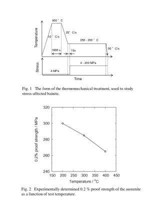
900 °C 25°C/s 10 °C/s Temperature 250 - 350 °C 50 °C/s 1800 s 15s 4 - 200 MPa Stress 4 MPa Time Fig. 1 The form of the thermomechanical treatment, used to study stress-affected bainite. Fig. 2 Experimentally determined 0.2 % proof strength of the austenite as a function of test temperature.
-1800 GMECH -1600 GCHEM -1400 -1200 -1000 Free energy / J mol-1 -800 -600 -400 Stored energy of bainite -200 0 250 º C 300 º C 350 º C Umemoto Shipway et al. [12] et al. [13] at 360 º C at 350 º C Fig.3 Chemical and mechanical components of the driving force for the growth of bainite.
(a) (b) Fig.4 Change in radial strain associated with the bainite transformation (a) at various transformation temperatures and (b) as a function of elastic stresses during transformation at 300 ºC.
Fig.5 Volume percent of bainite as a function of stress applied during the transformation, and the transformation temperature. Fig. 6 Transformation kinetics at various transformation temperatures and stresses.
HV 527 HV 644 HV 725 HV 579 HV 708 HV 777 25m 200 MPa 4 MPa 0.5 h 1 h 2 h Fig. 7 Optical micrographs of bainitic microstructure transformed under the influence of an applied compressive stress. The stress axis is vertical in each case. The transformation is at 300 ºC.
25m HV 576 HV 517 HV 429 HV 574 HV 508 HV 409 4 MPa 200 MPa 350 ºC, 5 h 300 ºC, 5 h 250 ºC, 12 h Fig. 8 Optical micrographs of bainite transformed under the influence of an applied compressive stress. The stress axis is vertical in each case.
(a) (b) 5 m 5 m Fig. 9 Typical scanning electron micrographs of bainite transformed under the influence of an applied stress (a) 4 MPa and (b) 200 MPa at 300 °C for 5 hours. The stress axis is vertical in each case.
Fig.10 Approximate distribution of bainite sheaf traces with respect to longitudinal axis of sample.
(a) (b) 20m Fig.11 Orientation imaging maps of bainite formed at 300 ºC for 5 hours under the influence of an applied compressive stress of (a) 4 MPa and (b) 200 MPa. The stress axis is vertical in each case.