Basic Electronics and Truth Tables for Beginners
Learn about truth tables, Boolean variables, Boolean operators, and logic statements. Understand how to represent standard Boolean operators and how to generate truth tables. Explore examples of sum of products and minterms.

Basic Electronics and Truth Tables for Beginners
E N D
Presentation Transcript
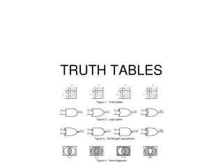
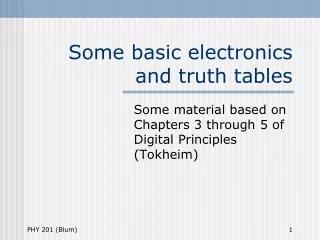
Some basic electronics and truth tables Some material on truth tables can be found in Chapters 3 through 5 of Digital Principles (Tokheim)
Logic Digital Electronics • In Logic, one refers to Logical statements (propositions which can be true or false). • What a computer scientist would represent by a Boolean variable. • In Electronics, one refers to inputs which will be high or low.
Boola Boola! • The expression (Booleans) and the rules for combining them (Boolean algebra) are named after George Boole(1815-64), a British mathematician.
Boolean operators • AND: when two or more Boolean expressions are ANDed, both must be true for the combination to be true. • OR: when two or more Boolean expressions are ORed, if either one or the other or both are true, then the combination is true. • NOT: takes one Boolean expression and yields the opposite of it, true false and vice versa.
Our Notation • NOT is represented by a prime or an apostrophe. • A’ means NOT A • OR is represented by a plus sign. • A + B means A OR B • AND is represented by placing the two variables next to one another. • AB means A AND B • The notation is like multiplication in regular algebra since if A and B are 1’s or 0’s the only product that gives 1 is when A and B are both 1.
Other Notations • Ā means NOT A • A means NOT A • AB means A OR B • A&B means A AND B • Tokheim uses the overbar notation for NOT, but we will use the prime notation because it is easier to type.
Other vocabulary • We will tend to refer to A and B as “inputs.” (Electronics) • Another term for them is “Boolean variables.” (Programming) • Still another term for them is “propositions.” (Logic) • And yet another term for them is “predicates.” (Logic and grammar)
(AB)’ A’B’ Note that the output is different
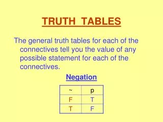
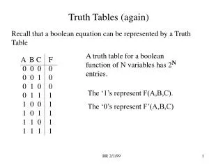
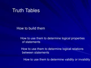
A Truth Table • A Truth table lists all possible inputs, that is, all possible values for the propositions. • For a given numbers of inputs, this is always the same. • Then it lists the output for each possible combination of inputs. • This varies from situation to situation.
The true one • Traditionally we take a 1 to represent true and a 0 to represent false. • This is just a convention. • In addition, we will usually interpret a high voltage as a true and a low voltage as a false.
Generating Inputs • The truth-table inputs consist of all the possible combinations of 0’s and 1’s for that number of inputs. • One way to generate the inputs for is to count in binary. • For two inputs, the combinations are 00, 01, 10 and 11 (binary for 0, 1, 2 and 3). • For three inputs, the combinations are 000, 001, 010, 011, 100, 101, 110 and 111 (binary for 0, 1, 2, 3, 4, 5, 6 and 7). • For n inputs there are 2n combinations (rows in the truth table).
Expressing truth tables • Every truth table can be expressed in terms of the basic Boolean operators AND, OR and NOT operators. • The circuits corresponding to those truth tables can be build using AND, OR and NOT gates. • The input in each line of a truth table can be expressed in terms of AND’s and NOT’s.
Note that these expressions have the property that their truth table output has only one row with a 1.
It’s true; it’s true • The following steps will allow you to generate an expression for the output of any truth table. • Take the true (1) outputs. • Write the expressions for that input line (as shown on the previous slide). • Then feed all of those expressions into an OR gate. • Sometimes we have multiple outputs (e.g. bit addition had a sum output and a carry output). Then each output is treated separately.
Example: Majority Rules If two or more of the three inputs are high, then the output is high.
Row Expressions The highlighted rows correspond to the high outputs.
Sum of products • Each row is represented by the ANDing of inputs and/or inverses of inputs. • E.g. A’BC • Recall that ANDing is like Boolean multiplication • The overall expression for the truth table is then obtained by ORing the expressions for the individual rows. • Recall that ORing is like Boolean addition • E.g. A’BC + AB’C + ABC’ + ABC • This type of expression is known as a sum of products expression.
Minterm • The terms for the rows have a particular form in which every input (or its inverse) is ANDed together. • Such a term is known an a minterm.
Majority rules • A´BC + AB´C + ABC´ + ABC NOTs OR ANDs
Majority rules • A´BC + AB´C + ABC´ + ABC NOTs OR ANDs
Another Example (Cont.) • A’B’C’ + A’BC’ + AB’C + ABC • The expression one arrives at in this way is known as the sum of products. • You take the product (the AND operation) first to represent a given line. • Then you sum (the OR operation) together those expressions. • It’s also called the minterm expression.
Yet Another Example 2 (Cont.) • A’B’C + A’BC’ + A’BC + AB’C’ + AB’C + ABC’ + ABC • But isn’t that just the truth table for A+B+C? • There is another way to write the expression for truth tables.
Another Example (Cont.) In this approach, one looks at the 0’s instead of the 1’s.
Another Example (Cont.) • One writes expressions for the lines which are 1 everywhere except the line one is focusing on. • Then one ANDs those expressions together. • The expression obtained this way is known as the product of sums.
Expressions This is not yet a truth table. It has no outputs.
Return to Example 1 (Cont.) • The product of sums expression is (A+B+C’)(A+B’+C’)(A’+B+C)(A’+B’+C) • Each term has all of the inputs (or their inverses) ORed together. • Such terms are known as maxterms. • Another name for the product of sums expression is the maxterm expression.
Venn Diagram • A Venn diagram is a pictorial representation of a truth table. • Venn diagrams come from set theory. • The correspondence between set theory and logic is that either one belongs to a set or one does not, so set theory and logic go together.
Venn (Cont.) Does not belong to set False Belongs to set True
Overlapping sets A true, but B false B true, but A false A and B true A false and B false The different regions correspond to the various possible inputs of a truth table. The true outputs are represented by shaded regions of the Venn diagram.
Ohm’s Law • V = I R, where • V is voltage: the amount of energy per charge. • I is current: the rate at which charge flows, e.g. how much charge goes by in a second. • R is resistance: the “difficulty” a charge encounters as it moves through a part of a circuit.
Circuit • A circuit is a closed path along which charges flow. • If there is not a closed path that allows the charge to get back to where it started (without retracing its steps), the circuit is said to be “open” or “broken.” • The path doesn’t have to be unique; there may be more than one path.
An analogy • A charge leaving a battery is like you starting the day after a good night’s rest; you are full of energy. • Being the kind of person you are, you will expend all of your energy and collapse utterly exhausted into bed at the end of the day; the charge uses up all of its energy in traversing a circuit.
Analogy (cont.) • You look ahead to the tasks of the day and divide your energy accordingly – the more difficult the task, the more of your energy it requires (resistors in series). • The tasks are resistors, so more energy (voltage) is used up working through the more difficult tasks (higher resistances). • The higher the resistance, the greater the voltage drop (energy used up) across it.
One charge among many • You are just one charge among many. • If the task at hand is very difficult (the resistance is high), not many will do it (the current is low); • V=IR, if R is big, I must be small. • If the task is easy, everyone rushes to do it. • V=IR, if R is small, I will be large.
More energetic • If we had more energy, more of us would attempt a given task. • V=IR, if V is bigger, I is bigger. • If we are all tired out, few of us will perform even the most basic task. • V=IR, if V is small, I will be small.
Given the choice • Given the choice between a difficult task and an easy task, most will choose the easier task. • If there is more than one path, most take the “path of least resistance” (resistors in parallel).