Download
1 / 29
290 likes | 310 Views
Explore a cutting-edge event-driven read-out system designed for a novel PET scanner with advanced gamma reconstruction capabilities. This system maximizes accuracy and efficiency in medical imaging applications by leveraging Compton-enhanced 3D gamma reconstruction technology.

E N D
An Event Driven Read-out System for a Novel PET Scanner with Compton Enhanced 3D Gamma Reconstruction A. Dragone1, 2, F. Corsi 1, 2, C. Marzocca 1, 2, P. Losito 2, D. Pasqua 2, 3 A. Argentieri 2, E. Nappi 3, R. De Leo 3, J. Séguinot 4, A. Braem 5, E. Chesi 5, C. Joram 5, P. Weilhammer 5, F. Garibaldi 6, H. Zaidi 7 1 Dipartimento di Ingegneria Elettrotecnica ed Elettronica - Politecnico di Bari 2 Microlaben S.r.l. - Bari 3 Istituto Nazionale di Fisica Nucleare - Bari 4 Collège de France, Paris 5 PH Department, CERN, Geneva 6 Istituto Superiore di Sanità, Roma 7 Division of Nuclear Medicine, Geneva University Hospital, Geneva CIMA meeting - Perugia
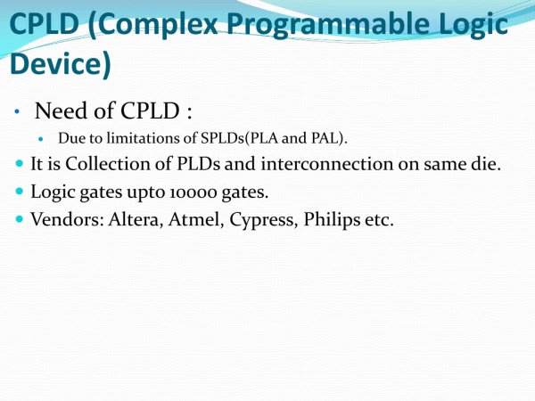
Microlaben S.r.l., spin-off of the Politecnico di Bari was born with the aim of transferring the experience developed in the microelectronics research group of the Politecnico di Bari and its research results, in innovative field of applications suitable for the market. • Skills • Programmable Logic based device Design (CPLD, FPGA and microcontrollers) • Front-end and Read-out systems for photodetectors • Hardware/firmware design for data acquisition and transmission systems • Fields of interest: • Medical Imaging • Environment monitoring • Telecomunications CIMA meeting - Perugia
Outline • 3D PET scanner architecture (main features) • The Data Acquisition System (DAQ) Design • Main Constrains • Trigger generation • Acquisition and Transfer Rates • DAQ Architecture • The Backplane card (BP) • The Read-out card (RO) • The Process Controller (CP) • Logic Design Verification • Future Tasks and Conclusions CIMA meeting - Perugia
3D PET Scanner Architecture A Novel Geometrical Concept A ring of 16 modules, each one composed of a matrix of 16x13 axially oriented LYSO (LSO) crystal bars, which is read-out by two Hybrid Photon Detectors. z References: J. Séguinot, A. Bream, E. Chesi, et. al., Novel geometrical concept of high performance brain PET scanner – Principle, design and performance, CERN preprint PH-EP/2004-050, in preparation for publication on NIMA; CIMA meeting - Perugia
The Hybrid Photon Detector (HPD) • A bialkali photocathode with a quantum efficiency of about 18% at 400nm • A silicon sensor segmented into 208 individual diodes • Gain of about 3000 • 1:1 image of the photon pattern on the silicon sensor (proximity focusing) • Possibility to read-out the Si back plane • Integrated self- triggering front-end electronics (VaTa GP5 chips) Features Full 3D image reconstruction • accurate and uniform spatial resolution in the transaxial (x-y) plane, good precision reconstructing of the axial coordinate (z) of the interaction point • reduction of parallax effect Compton enhanced sensitivity • reconstruction of a fraction of events which underwent Compton scattering in the detector CIMA meeting - Perugia
The Data Acquisition System Architecture Main Constrains • The requirement to perform coincidence check minimizing the detection of accidental events • The need to Minimize the dead time between subsequent acquisitions • The requirement to detect and analyze gamma interactions, which involve, both total photoelectric conversion and Compton scattering in the detector CIMA meeting - Perugia
I - The requirement to perform coincidence minimizing the detection of accidental events “Good” PET event : time-coincident detection of two annihilation quanta of 511 keV energy emitted in a back-to-back configuration To reduce the probability of accidentals, the determination of an event should be done in a coincidence time window (CTW) as narrow as possible. The minimum time window will depend on the jitter among the triggering signals (FORMs) of the HPDs (2-3 ns). Events must be tracked in a unique CTW shared among the modules. On the contrary, allowing each module to start its own time window would imply that good events could be lost or false coincidences could be detected. CIMA meeting - Perugia
I - The requirement to perform coincidence minimizing the detection of accidental events The definition of a meaningful angle of acceptance allows to reduce the detection of accidental false coincidences, discarding the geometrical configurations without a physical meaning. Only the couple of modules that fulfill a coincidence in the CTW (if they exist) are read out, while the other modules are reset promptly, in order to be ready to accept coincidences with different modules. Two modules in coincidence define a CHAIN and chains are set dynamically by the process controller card on the basis of the coincidence analysis. CIMA meeting - Perugia
II - Minimize the dead time between subsequent acquisitions Different levels of parallelism Module Level two modules in coincidence (i.e. a chain), are read-out in parallel Chain Level chains are read-out in parallel Several Independent Event Driven and Parallel Read-out Chains CIMA meeting - Perugia
II - Minimize the dead time between subsequent acquisitions Several Independent Event Driven and Parallel Read-out Chains RT Read-Out Time CTW Coincidence Time Window CIMA meeting - Perugia
II - Minimize the dead time between subsequent acquisitions When a coincidence between two modules is detected a suitable signal must be provided to the front-end in order to avoid the generation of triggers from other channels before completing the read-out. The VaTaGp5 Disable Late Trigger (DLT) function can be used. Drawbacks How to select a single event ? DLT signal can be generated only after the end of the coincidence analysis that is based on FORM signals from the modules. Coincidence Analysis Triggers FOR FORM DLT VaTaGp5 Unacceptable delay CIMA meeting - Perugia
How to Select a single Event ? To address this issue, signals derived from the HPDs silicon back plane are acquired by dedicated cards i.e. the BP cards. This fast signal can be used to generate the FORM instead of the triggers produced by the VaTaGP5 chips. Solution ? To select a single event Trigger ~ 60 ns t BP card Coincidence Analysis DLT Delay ? FORM Is it possible to sense the backplane and provide the DLT in less than 60 ns ? !!!!! CIMA meeting - Perugia
Sensing the Backplane Q Ip Shaper Ci ex. SNJ3600 or 2 J110 Si detector backplane: Area ~ 20 cm2 Cdet ~ 400 pF Q ~ 1.5 – 2x10⁶ e- Tc ~ 20 - 30 ns VDC~ 40 V A discrete charge sensitive preamplifier with a 20ns shaper should be able to sense ~ 1/2 of the total charge generated in the detector, providing a shaped pulse with ~ 40ns peaking time and a width of ~ 100ns (depending on the shaper order) without significant distortion. CIMA meeting - Perugia
III - The requirement to detect and analyze gamma interactions, which involve, both total photoelectric conversion and Compton scattering in the detector This third constraint requires running the FE electronics with a relatively low detection threshold (50keV) in order to detect and reconstruct the recoil electron of the primary Compton scattering. The low threshold prevents the rejection of a large fraction of gammas which underwent Compton scattering in the organic tissue Proportional to the total energy converted in the sensor, since back planes cover the full detector area. Proportional to the total energy converted in the scintillator block Pre Amp Dual input shaper Pole Zero comp. Integrator FORM Pole Zero comp. Pre Amp Disc. Threshold Reject low energy gamma rays (after Compton scattering in the patient), thus the detection of Compton interactions in the scintillator matrix is not compromised. CIMA meeting - Perugia
Acquisition and Transfer Rates In the NEMA-NU2 test protocol conditions, with a phantom radiotracer concentration of 0,35Ci/ml (total activity =81.4 MBq) we can assume: Average hit rate per module: RM = 1.8 MHz (mean time between two hit tM = 0.56 us) Average rate of events (coincidence on a generic pair of modules) within a CTW = 10 ns: RC = RM*RM*CTW = 32.4 KHz (mean time between two events on the same couple of module tC = 30 us) Average Read-out Time per chain: tR = (N ADC cycles + N rclock cycles) x Tclk + tFPGA = (3+3)*50ns+350ns= 0.75 us CIMA meeting - Perugia
Acquisition and Transfer Rates Checking 1:5 (within a meaningful angle of acceptance) Number of possible module pairs combinations: NC=40 Average rate of detected coincidences: RS=NcxRM = 1.3 MHz (mean time between coincidences tS=0.77 us) Average rate of detected coincidencesper chain: RCM=Rs/Nchains= 163 kHz (mean time between coincidence per chain tCM = 6.1 us) tR< tCM the readout of the chains is feasible Encoding each channel information with 32 bits, the average number of bits per event is W=32*3 bits, thus: Average module throughput: RbM =RCMxW= 15.6 Mb/s < 30 Mbit/s (USB rate pre module) Average system throughput: RbS = RbM*Nmod= 250Mb/s RbS < USB2.0 max transfer rate = 480 Mb/s the data storage is feasible CIMA meeting - Perugia
The Data Acquisition System • The data acquisition system is based on 3 building blocks: • Backplane Cards (BP cards) • One BP card per module. It extracts the triggering signals from the module detectors and process them in order to detect only meaningful events. • The Read-Out Cards (RO cards) • One RO card per module. It performs the read-out of the modules, according to the sparse read-out mode of the VaTaGP5 chip. • The Process Controller Card (CP card) • One CP card per system. It controls the synchronization of both the BPs and the ROs cards and manages the data transfer into a server-like workstation. CIMA meeting - Perugia
The Data Acquisition System CIMA meeting - Perugia
The Backplane card (BP card) Features Amplifiers Sense the back planes of the HPDs of a module and generate the back plane signals. The analog adder Performs a suitable weighted analog sum. The signal is sent to a double threshold discriminator that generates the FORM. DLT logic Generates the DLT signal to the front-end when the ER signal, which enables the read-out, arrives from the CP or it resets the front-end in a self reset mode when no ER signal arrives (false or accidental events). CIMA meeting - Perugia
The Read-out card (RO card) Features ADC converters Two 3 stage, 12 bits pipeline flash ADC. The Module Processor • Performs the readout of the two HPDs of the module in parallel, according with the sparse read-out mode procedure of the VaTaGP5 chips. • Acquires and stores the data in an internal FIFO buffer. • Performs a coincidence check in order to verify that only one event has been detected. Bias and Control Interface Provides the bias signals and the control signals required by the VaTaGp5 chips. CIMA meeting - Perugia
The Module Processing Logic The card can be used as a stand alone read-out system that allows reading out up to 16 daisy chained chips per channel (2x16). CIMA meeting - Perugia
The Process Controller Card Features • Senses the FORMs and enables the CTW timer. • Counts FORMS within the CTW in order to detect coincidences. • Defines a chain when two modules are found in coincidence within a meaningful angle of acceptance assigning them a busy flag and an event number. • Starts the chain read-out • Resets the FORM register to perform subsequent analysis on the remaining free modules. • Controls data storage CIMA meeting - Perugia
READ OUT LOGIC 32 bit – ch2 0110 16 bit up –ch1 16 bit down –ch2 16 bit up –ch2 16 bit down –ch1 0010 32 bit - ch1 Design Verification PATTERN GENERATOR 16 bit OUT 8 bit RANDOM CIMA meeting - Perugia
Design Verification: sparse readout – 1 hit per HPD 32 bit Input Word: { 9 bit Event Counter, 11 bit Channel Address, 12 bit ADC Output } ch_a: 000000100 00000011001 011011101110 ch_b :000000100 00100011001 010001111101 CIMA meeting - Perugia
Design Verification: sparse readout – different number of hits per HPD No Check Coincidence → No Store Data → Reset CIMA meeting - Perugia
Design Verification: sparse readout – 1 hit per HPD CIMA meeting - Perugia
Design Verification: sparse readout – different number of hits per HPD CIMA meeting - Perugia
Conclusions Completed Tasks • Logic design and Verification of the control protocol to perform VaTaGp5 read-out modes: • - Serial read-out • - Sparse read-out • - Sparse read-out with neighbor channels • - Random Access Read-out • - Random Access Read-out with neighbor channels • Logic design and Verification of the data transferring protocol from the RO card to the local PC: • - 2 parallel 32 bit input channel to acquire the VATA and PC Card output data • - 2 4K*16 bit FIFO to store data temporary • - 1 16 bit output channel to send to USB 2.0 controller the data Future Tasks • PCB Design of the RO card (under development) • Logic Design of the CP logic (under development) • Design of the Backplane amplifier and the BP card • Design of a software interface for the data acquisition • Solve the unnumbered troubles we are approaching and get around pitfalls ! CIMA meeting - Perugia
What is the probability of success ? CIMA meeting - Perugia