Download
1 / 23
230 likes | 391 Views
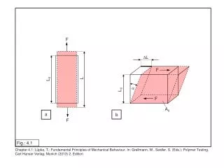
Chapter 10.4-10.8: Vectors, AC & L/C Behaviour. Vectors: The Basics. Vectors always have two key components: Direction Magnitude Vectors are often used to: Describe forces since forces have both direction and magnitude Define mathematical planes. Vectors: Anatomy.

E N D
Vectors: The Basics • Vectors always have two key components: • Direction • Magnitude • Vectors are often used to: • Describe forces • since forces have both direction and magnitude • Define mathematical planes
Vectors: Anatomy What is the length (magnitude) and the direction of vector “C”? Lets start with the easy value: the length (magnitude). We can find this using the following equation: Now lets find the direction of “C” C Therefore, the vector “C” has a magnitude of ~14.4 and a direction of ~56° C2 = A2 + B2 Or C = sqrt(A2 + B2) By using cotangent, we can determine the angle theta (θ) as follows: C = 14.4 B = 12 Θ= tan-1 (B/A) Θ = cot (12 / 8) Θ = ~56° C = sqrt(82 + 122) C = ~14.4 θ Θ = ~56° A = 8
Vectors: AC = Rotating Vectors • Vectors can be used to represent voltage and current in an AC system • We use angular velocity ω (omega) to represent a rotating vector and its value is: ω = 2πf • Where f = frequency (of rotation) • This concept comes up later …
Vectors: Angular Velocity • By convention, we define a rotating vector to have an angular velocity in the counter-clockwise direction
AC: Resistors • Voltage (E) and current (I) vectors rotate in phase so their phase angle is 0° • This means that the magnitude of both E and I increase and decrease at exactly the same time • Restated: voltage and current go up and down with the alternating current flow at the same time • Resistors behave with AC the same as they do with DC, but we have to use the Vrms when we use Ohm’s Law
AC: Impedance • When considering an alternating flow of current, Ohm’s Law is re-written as: Erms = I x Z • The new term “Z” is impedance in Ω
AC: Resistors – E and I • Since the vectors are in phase, only the magnitudes of E and I are different in the resistor (whose Impedance is “Z”) • The rotating vectors are co-linear (0 phase angle) but have different magnitudes as demonstrated below: E = 10V Z = 40Ω I = ?
AC: Real Components • Consider for a moment that most components have both inductive and capacitive characters • What effect do you think this might have on the alternating current and vice-versa?
AC: Inductors (ELI) • In an inductor, the voltage (E) “leads” the current (I) by 90° E = 40V XC = 80Ω I = ?
XL: Inductive Reactance • There is a concept called reactance which in many ways mirrors resistance • Two key differences: • power is not lost as heat, it is merely temporarily stored in a magnetic field • Inductive reactance is a function of frequency EL = IL x XL • XL is the inductive reactance in Ω
XL: Calculating its value XL = ωL • Recall from earlier that ω = 2πf XL = 2πf L • Where: • XL = inductive reactance (Ω) • f = frequency (Hz) • L = inductance (Henrys)
XL: Example Calculation • If you have an inductor whose value is 20mH and you pass an alternating current at a frequency of 10MHz, what is the inductive reactance of the inductor? XL = 2πf L • XL = (2π)(10 x 106 HZ)(20 x 10-3H) • XL = (6.28)(10)(20)(106)(10-3) • XL = (6.28)(200)(103) • XL = (6.28)(2)(100)(103) • XL = (12.56)(102)(103) • XL = (1.256)(101)(102)(103) • XL = 1.256 x 10⁶Ω • XL ≈ 1.25MΩ M = mega = 106 m = milli = 10-3 Group exponential values 106 x 10-3 = 10{6+ (-3)} Recall we must always work in “base” units Recall: since M = 106 ; 106 = M !!
XL: Frequency & Inductance Impedance frequency
XL: Vector Analysis So the AC source generates 5Vac and the voltage leads the current by 90° and the phase angle of the source leaving the inductor is ≈53° The length (magnitude) of the resultant vector is equal to the EMF generated by the AC source! EXL= 4 ER= 3 I =0.1A Given the following circuit, lets use vector analysis to determine the EMF generated by the AC source. Consider the circuit to be an inductor which has both resistance and inductance. The current flowing in the circuit is known to be 0.1A and the frequency of the AC source is known, therefore by Ohm’s law, we can calculate the voltages developed at each “point” in the circuit by vector analysis. Knowing the voltages developed by the “component values” of XL and R we can determine the voltage of the frequency generating source as follows: Esource = 5 What is the phase angle (φ) of the resultant (Esource) vector? φ = tan-1(EXL/ ER) φ = tan-1( 4 / 3 ) φ ≈ 53° We know that Esource = 5 by the equation: C 2 = A2 + B2 C = √(A2 + B2) We can also cheat and use the “tip-to-tail” method seen to the left. φ ≈ 53° φ
XL: Changing Values Lets investigate how changing values of a component can affect the phase angle of an AC source when leaving an inductor. Esource ≈ 8.5 Φ ≈ 69° Esource2 ≈ 8.9 Φ ≈ 26°
XC: Capacitive Reactance XL = 1 . ωC • Recall from earlier that ω = 2πf XL = (2πf C)-1 • Where: • XC = capacitive reactance (Ω) • f = frequency (Hz) • C = capacitance (Farads)
AC: Capacitors (ICE) • In a capacitor, the current (I) “leads” the voltage (E) by 90° • Notice that when voltage is zero, the current at its maximum positive value, opposing a change in voltage by allowing a flow of electrons E = 25V XL = 100Ω I = ?
XC: Changing Values C1 < C2 < C3 Xc f (Hz)
AC: Power • In AC systems, power has two values: • True • Apparent • True power is the actual power consumed by a circuit • Apparent power is the total power which would have been consumed if the circuit were entirely resistive
AC: Power Factor • If a load were purely resistive (ie. Baseboard heaters) power factor is 1.0 • 100% of power consumed is metered correctly • In inductive (eg. motors) or capacitive loads, not all power is metered • “apparent power” is the product of E * I • Power factor of > 1 means you are “stealing” power from the mains provider
AC: Power Factor |P| = |S|* |cosφ| • P = real power • S = apparent power (in VA) • Φ = phase angle • What this effectively means is that as Φ → 90° power → 0 since cos(90°) = 0
AC: Power Factor • So in industry and where inductive loads are used, how could you correct the phase angle? • Large capacitors will correct the phase angle and return it to nearly 0 depending on the value of the capacitor • What about the case where a load is primarily capacitive? • … resonance lies ahead …