Download

1 / 15
190 likes | 426 Views
Physics 2102 Jonathan Dowling. Lecture 30: FRI 27 MAR 09 Ch. 31.4–7: Electrical Oscillations, LC Circuits, Alternating Current. EXAM 03: 6PM THU 02 APR LOCKETT 5 EXAM 03 REVIEW: 6PM WED 01 APR NICHOLSON 130.

E N D
Physics 2102 Jonathan Dowling Lecture 30: FRI 27 MAR 09 Ch. 31.4–7: Electrical Oscillations, LC Circuits, Alternating Current
EXAM 03: 6PM THU 02 APR LOCKETT 5 EXAM 03 REVIEW: 6PM WED 01 APR NICHOLSON 130 The exam will cover: Ch.28 (second half) through Ch.32.1-3 (displacement current, and Maxwell's equations). The exam will be based on: HW08 – HW11. The formula sheet for the exam can be found here: http://www.phys.lsu.edu/classes/spring2009/phys2102/formulasheet.pdf You can see examples of old exam IIIs here: http://www.phys.lsu.edu/classes/spring2009/phys2102/Test3.oldtests.pdf Final Day to Drop Course: TODAY FRI 27 MAR
Damped LCR Oscillator C L R Ideal LC circuit without resistance: oscillations go on for ever; w = (LC)–1/2 Real circuit has resistance, dissipates energy: oscillations die out, or are “damped” Math is complicated! Important points: • Frequency of oscillator shifts away from w = (LC)-1/2 • Peak CHARGE decays with time constant = • QLCR=2L/R • For small damping, peak ENERGY decays with time constant • ULCR= L/R
Summary • Capacitor and inductor combination produces an electrical oscillator, natural frequency of oscillator is =1/√LC • Total energy in circuit is conserved: switches between capacitor (electric field) and inductor (magnetic field). • If a resistor is included in the circuit, the total energy decays (is dissipated by R).
Alternating Current: To keep oscillations going we need to drive the circuit with an external emf that produces a current that goes back and forth. Notice that there are two frequencies involved: one at which the circuit would oscillate “naturally”. The other is the frequency at which we drive the oscillation. However, the “natural” oscillation usually dies off quickly (exponentially) with time. Therefore in the long run, circuits actually oscillate with the frequency at which they are driven. (All this is true for the gentleman trying to make the lady swing back and forth in the picture too).
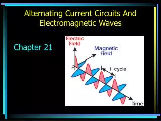
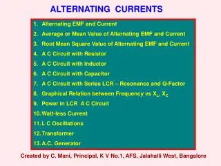
Alternating Current: We have studied that a loop of wire, spinning in a constant magnetic field will have an induced emf that oscillates with time, That is, it is an AC generator. AC’s are very easy to generate, they are also easy to amplify and decrease in voltage. This in turn makes them easy to send in distribution grids like the ones that power our homes. Because the interplay of AC and oscillating circuits can be quite complex, we will start by steps, studying how currents and voltages respond in various simple circuits to AC’s.
AC Driven Circuits: 1) A Resistor: For time dependent periodic situations it is useful to represent magnitudes using “phasors”. These are vectors that rotate at a frequency wd , their magnitude is equal to the amplitude of the quantity in question and their projection on the vertical axis represents the instantaneous value of the quantity under study. Resistors behave in AC very much as in DC, current and voltage are proportional (as functions of time in the case of AC), that is, they are “in phase”.
AC Driven Circuits: 2) Capacitors: Capacitors “oppose a resistance” to AC (reactance) of frequency-dependent magnitude 1/wd C (this idea is true only for maximum amplitudes, the instantaneous story is more complex).
AC Driven Circuits: 3) Inductors: Inductors “oppose a resistance” to AC (reactance) of frequency-dependent magnitude wd L (this idea is true only for maximum amplitudes, the instantaneous story is more complex).
Transmission lines Erms=735 kV , Irms = 500 A Home Step-down transformer Step-up transformer 110 V T2 T1 R = 220Ω Power Station Ptrans=iV = “big” Pheat=i2R = “small” Solution: Big V! (31-24)
![L 27 Electricity and Magnetism [4]](https://cdn0.slideserve.com/291521/l-27-electricity-and-magnetism-4-dt.jpg)