Download
1 / 33
360 likes | 556 Views
Chapter 22. Alternating-Current Circuits and Machines February 25 th , 2013. summary of this class: RMS Voltage, Current, Power. 1 resistor. 1 capacitor. current leads. summary of this class. 1 induc tor. current lags. Resistor in AC circuit. P = V max I max sin 2 (2 π ƒt ).

E N D
Chapter 22 Alternating-Current Circuits and Machines February 25th, 2013
1 resistor 1 capacitor current leads summary of this class 1 inductor current lags
Resistor in AC circuit P = Vmax Imax sin2 (2πƒt) Capacitor in AC circuit I = Imax sin (2πƒt + Φ) where Φ = π/2 P = VI = VmaxImaxsin(2πƒt) cos(2πƒt) Pavg = 0 Inductor in AC circuit V = L (ΔI/Δt) = Vmax sin (2πƒt) • I = -Imaxcos (2πƒt) • I = Imax sin (2πƒt + Φ) where Φ = -π/2 P = VI = -VmaxImaxsin(2πƒt) cos(2πƒt) Pavg = 0
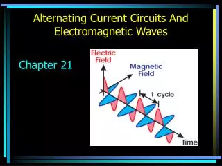
AC Circuit Introduction • AC stands for alternating current • An AC power source produces an electric potential that varies with time • There is a frequency and maximum voltage associated with the potential • Household electrical energy is supplied by an AC source • Standard frequency is 60 Hz • AC circuits have numerous advantages over DC circuits
AC Generators • The figure shows an alternating-current generator
Resistor in an AC Circuit • If a circuit consists of an AC generator and a resistor • Then the voltage across the output of the AC source varies with time according to • V = Vmax sin (2πƒt) • V is the instantaneous voltage
Resistor, cont. • Applying Ohm’s Law: • The voltage varies sinusoidally • Therefore the current does too:
RMS Voltage • RMS values are the norm to specify current and voltage values when these vary with time • RMS stands for Root Mean Square • For the voltage
RMS Current • The root-mean-square value can be defined for any quantity • For the current • The Vrms and Irmsare typically used to specify the properties of an AC circuit
Power • The instantaneous power is the product of the instantaneous voltage by the instantaneous current • P = IV • Since both I and V vary with time, the power also varies with time • P = Vmax Imax sin2 (2πƒt)
Power, cont. • Devices come with a power rating • A single number that tells you about the power usage of the device • The instantaneous power varies between Vmax Imax and 0 • The average power is ½ the maximum power • Pavg = ½ (Vmax Imax ) = VrmsIrms • Ohm’s Law can again be used to express the power in different ways
Phasors • AC circuits can be analyzed graphically using a phasor diagram • An arrow has a length Vmax • The arrowtailis at the origin • The arrowhead forms an angleθwith the horizontal axis • The angle varies with time according to θ = 2πƒt • The rotating arrow represents the voltage in an AC circuit • The arrow is called a phasor • A phasor is not a vector • A phasor diagram provides a convenient way to illustrate and think about the time dependence in an AC circuit
Phasors • The current in an AC circuit can also be represented by a phasor • The two phasors always form the same angle with the horizontal axis as time passes • The current and voltage are in phase • For a circuit with only resistors
AC Circuits with Capacitors • If an AC circuit contains a single capacitor • Then the instantaneous charge is q= CV = C Vmax sin (2πƒt) • The capacitor’s voltage and charge are in phase with each other
Current in Capacitors • The instantaneous current is the rate at which charge flows onto the capacitor plates in a short time interval • The currentI is the slope of the q-t plot • A plot of the current as a function of time can be obtained from these slopes
Current in Capacitors, cont. • The current is a cosine function I = Imaxcos (2πƒt) • Equivalently, due to the relationship between sine and cosine functions I = Imax sin (2πƒt+ Φ) where Φ= π/2
Capacitor Phasor Diagram • The current is out of phase with the voltage • The angle π/2 is called the phase angle Φ, between Vand I • For this circuit, the current and voltage are out of phase by 90o
Current Value for a Capacitor • The peak value of the current is • The factor Xc is called the reactance of the capacitor • Units of reactance are Ohms • Reactance and resistance are different because the reactance of a capacitor depends on the frequency • If the frequency is increased, the charge oscillates more rapidly and Δt is smaller, giving a larger current • At high frequencies, the peak current is larger and the reactance is smaller • A capacitor makes a high-pass filter
Power in a Capacitor • For an AC circuit with a capacitor P = VI = Vmax Imax sin (2πƒt) cos (2πƒt) • The average value of the power over many oscillations is 0 • Energy is transferred to and fro, between the generator and the capacitor • Energy is stored in the capacitor as electric potential energy and not dissipated by the circuit
AC Circuits with Inductors • If an AC circuit contains a single inductor • The voltage drop is V = L (ΔI/Δt) = Vmax sin (2πƒt) • The inductor’s voltage is proportional to the slope of the current-time plot
Current in Inductors • The instantaneous current oscillates in time according to a cosine function • I = -Imaxcos (2πƒt) • see plots
Current in Inductors, cont. • The current equation can be rewritten as I = Imax sin (2πƒt – π/2) • Equivalently, I = Imax sin (2πƒt + Φ) where Φ = -π/2
Inductor Phasor Diagram • The current is out of phasewrt the voltage • For this circuit, the current and voltage are out of phase by -90o • Remember, for a capacitor, the phase difference was +90o
Current Value for an Inductor • The peak value of the current is • The factor XL is called the reactance of the inductor • Units of inductive reactance are Ohms • As with the capacitor, inductive reactance depends on the frequency • As the frequency is increased, the inductive reactance increases • A capacitor makes a low-pass filter
Properties of AC Circuits +90° -90°
Power in an Inductor • For an AC circuit with an inductor P = VI = -Vmax Imax sin (2πƒt) cos (2πƒt) • The average value of the power over many oscillations is 0 • Energy is transferred from the generator during part of the cycle and from the inductor in other parts of the cycle • Energy is stored in the inductor as magnetic potential energy
Two capacitors with C1 = 4.5 µF and C2 = 1.9 µF are connected in series. What is the reactance of the equivalent capacitance, at 350 Hz? Problem 22.30
1 resistor 1 capacitor current leads summary of this class 1 inductor current lags
Resistor in AC circuit P = Vmax Imax sin2 (2πƒt) Capacitor in AC circuit I = Imax sin (2πƒt + Φ) where Φ = π/2 P = VI = VmaxImaxsin(2πƒt) cos(2πƒt) Pavg = 0 Inductor in AC circuit V = L (ΔI/Δt) = Vmax sin (2πƒt) • I = -Imaxcos (2πƒt) • I = Imax sin (2πƒt + Φ) where Φ = -π/2 P = VI = -VmaxImaxsin(2πƒt) cos(2πƒt) Pavg = 0