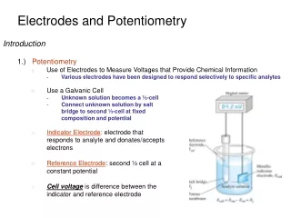
14-1 Reference Electrodes
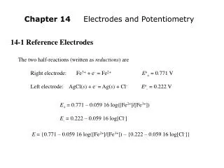
Chapter 14 Electrodes and Potentiometry. 14-1 Reference Electrodes. The two half-reactions (written as reductions ) are Right electrode: Fe 3+ + e - = Fe 2+ E o + = 0.771 V Left electrode: AgCl( s ) + e - = Ag( s ) + Cl - E o - = 0.222 V.

14-1 Reference Electrodes
E N D
Presentation Transcript
Chapter 14 Electrodes and Potentiometry 14-1 Reference Electrodes The two half-reactions (written as reductions) are Right electrode: Fe3+ + e- = Fe2+Eo+ = 0.771 V Left electrode: AgCl(s) + e- = Ag(s) + Cl-Eo- = 0.222 V E+ = 0.771 – 0.059 16 log([Fe2+]/[Fe3+]) E- = 0.222 – 0.059 16 log[Cl-] E = {0.771 – 0.059 16 log([Fe2+]/[Fe3+]) – {0.222 – 0.059 16 log[Cl-]}
The half-cell on the left in Figure 15-1 can be thought of a s a reference electrode. The reference electrode completes the redox reaction and provides a constant potential to the left side of the potentiometer.
Silver-Silver Chloride Reference Electrode2 The half-cell enclosed by the dashed line in figure 15-1 is called a silver-silver chloride electrode. Figure 15-4 shows a double-junction electrode that minimizes contact between analyte solution and KCl from the electrode. Ag | AgCl electrode: AgCl(s) + e- = Ag(s) + Cl-Eo = +0.222 V E(saturated KCl) = +0.197 V
Calomel Electrode The calomel electrode in Figure 15-1 is based on the reaction Calomel electrode:1/2Hg2Cl2(s) + e- = Hg(l) + Cl-Eo = +0.268 V Mercury(I) chlorideE(saturated KCl) = +0.197 V (calomel) A calomel electrode saturated with KCl is called a saturated calomel electrode, abbreviated S.C.E.
14-2 Indicator Electrodes Metal electrodes described in this section develop an electric potential in response to a redox reaction at the metal surface. Ion-selective electrodes, described later, are not based on redox processes. The most common metal indicator electrode is platinum, which is relatively inertㅡit does not participate in many chemical reactions. Ag+ + e- = Ag(s) Eo+ = 0.799 V Hg2Cl2(s) + 2e- = 2Hg(l) + 2Cl-E- = 0.241 V E = E+ - E- = {0.799 – 0.059 16 log(1/[Ag+])} – {0.241} Potential of Ag | Ag+ Potential of indicator electrode S.C.E. reference electrode E = 0.558 + 0.059 16 log [Ag+] (15-1) In Figure 7-9, we used a silver indicator electrode and a glass reference electrode.
We see from the example that a silver electrode is also a halide electrode, if solid silver halide is present.6 E = 0.558 + 0.059 16 log(Ksp/[Cl-])
Demonstration 14-1 Potentiometry with an Oscillating Reaction7 3CH2(CO2H)2 + 2BrO3- + 2H+ Malonic acid Bromate 2BrCH(CO2H)2 + 3CO2 + 4H2O Bromomalonic acid
Trace a shows what is usually observed. The potential changes rapidly during the abrupt colorless-to-yellow change and gradually during the gentle yellow-to-colorless change. Trace b shows two different cycles superimposed in the same solution. This unusual event occurred in a reaction that had been oscillating normally for about 30 min.11
14-3 What is a Junction Potential? Whenever dissimilar electrolyte solutions are in contact, a voltage difference called the junction potential develops at their interface. The junction potential puts a fundamental limitation on the accuracy of direct potentiometric measurements, because we usually do not know the contribution of the junction to the measured voltage. However, Cl- ion has a greater mobility than Na+.
14-4 How Ion-Selective Electrodes Work10 Ion-selective electrodes, discussed in the remainder of this chapter, respond selectively to one ion. Consider the liquid-based ion-selective electrode in Figure 15-8. The electrode is said to be “liquid based” because the ion-selective membrane is a hydrophobic organic polymer impregnated with a viscous organic solution containing an ion exchanger and, sometimes, a ligand that selectively binds the analyte cation, C+.
The key in this example is the ligand, L (called an ionophore), that is soluble inside the membrane and selectively binds analyte ion. The ligand, L, is chosen to have a high affinity for analyte cation, C+, and low affinity for other ions. ΔG due to change in solvent ΔG due to change in activity (concentration) ΔG due to transferbetween phases and activity difference ΔG due to charge imbalance
Electric potential difference across phase boundary between membrane and analyte: Very little C+ can diffuse out of the membrane because each C+ that enters the aqueous phase leaves behind one R- in the membrane. Constant Constant Constant
14-5 pH Measurement with a Glass Electrode The glass electrode used to measure pH is the most common ion-selective electrode. A typical pH combination electrode, incorporating both glass and reference electrodes in one body, is shown in Figure 15-9. Glass membrane selectively binds H+ Ag(s) | AgCl(s) | Cl-(aq) || H+(aq, outside) H+(aq, inside), Cl-(aq) | AgCl(s) | Ag(s) H+ outside glass electrode (analyte solution) H+ inside glass electrode Inner reference electrode Outer reference electrode
Metal ions in these hydrated gel regions of the membrane diffuse out of the glass and into solution. The reaction in which H+ replaces cations in the glass is an ion-exchange equilibrium (Figure 15-13). Equation 15-3 states that the voltage of the ideal pH electrode changes by 59.16 mV for every pH-unit change of analyte activity at 25oC.
Response of E = constant + β(0.059 16) log AH+(outside) glass electrode: E = constant – β(0.059 16) pH(outside) (at 25oC) (15-4) The value of β, the electromotive efficiency, is close to 1.00 (typically > 0.98).
Calibration a Glass Electrode Wash the electrode with distilled water and gently blot it dry with a tissue. Do not wipe it, because this action might produce a static charge on the glass.
Box 14-1 Systematic Error in rainwater pH Measurement: The Effect of Junction Potential oxidation SO2 + H2O H2SO3 H2SO4 Sulfurous acid Sulfuric acid
Errors in pH Measurement Standards. A pH measurement cannot be more accurate than our standards, which are typically ±0.01 pH unit. Junciton potential. A junction potential exists at the porous plug near the bottom of the electrode in figure 15-9. If the ionic composition of the analyte solution is different from that of the standard buffer, the junction potential will change even if the pH of the two solutions is the same (Box 15-1). This effect gives an uncertainty of at least ~0.01 pH unit. Junction potential drift. Most combination electrodes have a Ag | AgCl reference electrode containing saturated KCl solution. More than 350 mg Ag/L dissolve in the KCl, mainly as AgCl43- and AgCl32-. In the porous plug, KCl is diluted and AgCl can precipitate. If analyte solution contains a reducting agent, Ag(s) also can precipitate in the plug. Both effects change the junction potential, causing a slow drift of the pH reading (solid colored circles in Figure 15-14). You can compensate for this error by recalibrating the electrode every 2 h.
Sodium error. When [H+] is very low and [Na+] is high, the electrode responds to Na+ and the apparent pH is lower than the true pH. This is called the sodium error or alkaline error (Figure 15-15). Acid error. In strong acid, the measured pH is higher than the actual pH, perhaps because the glass is saturated with H+ and cannot be further protonated (Figure 15-15). Equilibration time. It takes time for an electrode to equilibrate with a solution. A well-buffered solution requires ~30 s with adequate stirring. A poorly buffered solution (such as one near the equivalence point of a titration) needs many minutes. Hydration of glass. A dry electrode requires several hours of soaking before it responds to H+ correctly.
Temperature. A pH meter should be calibrated at the same temperature at which the measurement will be made. Cleaning. If an electrode has been exposed to a hydrophobic liquid, such as oil, it should be cleaned with a solvent that will dissolve the liquid and then conditioned well in aqueous solution. The reading of an improperly cleaned electrode can drift for hours while the electrode re-equilibrates with aqueous solution. Measurement of pH differences between solutions can be accurate to about ±0.002 pH unit, but knowledge of the true pH will still be at least an order of magnitude more uncertain.
14-6 Ion-Selective Electrodes22, 23 Glass membranes for H+ and certain monovalent cations Solid-state electrodes based on inorganic salt crystals Liquid-based electrodes using a hydrophobic polymer membrane saturated with a hydrophobic liquid ion exchanger Compound electrodes with a species-selective electrode enclosed by a membrane that is able to separate that species from others or that generates the species in a chemical reaction.
Selectivity Coefficient The selectivity coefficient gives the relative response of the electrode to different species with the same charge: Selectivity coefficient:kA,X = (response to X)/(response to A) (15-7) Response of ion-selective electrode: (15-8)
BOX 14-2 Measuring Selectivity Coefficients for an Ion-Selective Electrode
Reminder: How Ion-Selective Electrodes Work An ion-selective electrode responds to the activity of free analyte, not complexed analyte. The discrepancy arose because the inductively coupled plasma measures all lead and the ion-selective electrode measures free Pb2+. Solid-State Electrodes A solid-state ion-selective electrode based on an inorganic crystal is shown in Figure 15-16. Doping means adding a small amount of Eu2+ in place of La3+. Response of F- electrode: E = constant – β(0.059 16) log AF-(outside) (15-9)
E = constant – β(0.059 16) log[F-]γF- = constant – β(0.059 16) log γF- - (0.059 16) log[F-] This expression is constant because γF- is constant at constant ionic strength
A liquid-based ion-selective electrode is similar to the solid-state electrode in Figure 15-16, except that the liquid-based electrode has a hydrophobic membrane impregnated with a hydrophobic ion exchanger (called an ionophore) that is selective for analyte ion (Figure 15-20). Response of Ca2+ electrode:
Breakthrough in Ion-Selective Electrode Detection Limits24 The colored curve in Figure 15-21 was obtained with the same electrode components, but the internal filling solution was replaced by a metal ion buffer (Section 15-7) that fixes [Pb2+] at 10-12 M.
Compound Electrodes Compound electrodes contain a conventional electrode surrounded by a membrane that isolates (or generates) the analyte to which the electrode responds. These electrodes can be used to measure gases in solution or in the gas phase. Numerous ingenious compound electrodes using enzymes have been built.29
14-7 Using Ion-Selective Electrodes Electrodes respond to the activity of uncomplexed analyte ion. Standard Addition with Ion-Selective Electrodes The medium in which the analyte exists is called the matrix. For complex or unknown matrixes, the standard addition method (Section 5-3) can be used. Standard addition plot for ion-seletive electrode: y b m x
Metal Ion Buffers An alternative is to prepare a metal ion buffer from the metal and a suitable ligand.
14-8 Solid-State Chemical Sensors36 Semiconductors and Diodes Semiconductors such as Si (Figure 15-25), Ge, and GaAs are materials whose electrical resistivity30 lies between those of conductors and insulators. A phosphorus impurity, with five valence electrons, provides one extra conduction electron that is free to move through the crystal (Figure 15-26b). An aluminum impurity has one less bonding electron than necessary, creating a vacancy called a hole, which behaves as a positive charge carrier. A semiconductor with excess conduction electrons is called n-type, and one with excess holes is called p-type.
A diode is a pn junction (Figure 15-27a). The diode is said to be forward biased. If the polarity is reversed (Figure 15-27b), electrons are drawn out of n-Si and holes are drawn out of p-Si, leaving a thin depletion region devoid of charge carriers near the pn junction. The diode is reverse biased and does not conduct current in the reverse direction.
Chemical-Sensing Field Effect Transistor The base of the field effect transistor in Figure 15-28 is constructed of p-Si with two n-type regions called source and drain. An insulating surface layer of SiO2 is overcoated by a conductive metal gate between source and drain. The potential of the gate therefore regulates the current flow between source and drain. The essential feature of the chemical-sensing field effect transistor in Figure 15-29 is the chemically sensitive layer over the gate. The voltage that must be applied by an external circuit to bring the current back to its initial value is the response to Ag+.


![Reference: [1] TeamSpace paper](https://cdn2.slideserve.com/3924279/reference-1-teamspace-paper-dt.jpg)


![Reference: [1]](https://cdn5.slideserve.com/9521244/5-sources-of-errors-5-2-noise-types-5-2-1-thermal-dt.jpg)