Bituminous Street Recertification
520 likes | 688 Views
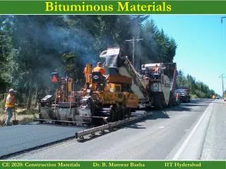
Bituminous Street Recertification. Initiatives. Initiative Items. Stone Matrix Asphalt (SMA) Longitudinal Joint Spec and other methods for longitudinal joint improvement. Asphalt Film Thickness Specification. Stone Matrix Asphalt (SMA) or Stone Mastic Asphalt. SMA.

Bituminous Street Recertification
E N D
Presentation Transcript
Bituminous Street Recertification Initiatives
Initiative Items • Stone Matrix Asphalt (SMA) • Longitudinal Joint Spec and other methods for longitudinal joint improvement. • Asphalt Film Thickness Specification
SMA • “Premium” mix based on European Technology • Designed for high traffic • Gap graded skeleton of high quality aggregate carries the load (55-80% +No.4) • Mastic consisting of asphalt (+6%), fines (8-12%), and fibers fill the voids.
Why SMA? • High stability with rutting and deformation resistance. • Increased durability (high binder content) • Good frictional properties • Reduced water spray • Lower traffic noise
Background • SMA was designed in Germany in the 1960’s as an overlay that would be resistant to studded tire damage. • SMA is widely used in Germany, the Netherlands, and Scandinavia as an overly or surface course to resist load-induced rutting and studded tire damage. • SMA introduced in the US in 1990. • 2 Projects in Minnesota in early 90’s; Lake City and TH 169.
How is SMA Different? • Gradation • Asphalt Content • Dust Content • Stabilizing Additives
Applications for SMA • High Traffic Volume Premium Surface Mixture • Ensure stone-on-stone contact • Increase film thickness mastic • Working together to provide long term pavement durability • Intersections • Round-abouts • Container facilities
SMA Overlays of PCC • High film thickness and gap graded structure helps to retard reflective cracking. • Polymer-modified binders add additional elasticity • High film thickness reduces raveling when reflective cracks occur.
Pilot SMA Specification • Use of a mineral filler. • Require use of asphalt stabilizer (fibers). • 100 design gyrations, 16% VMA, 4% voids. • Minimum asphalt set by combined aggregate specific gravity. • Minimum asphalt grade, PG 70-28 • Require bulking of cores by Corelok method. • Test strip required. • Minimum mat density, 94.0% of Gmm.
Mixing Temps • Supplier should provide Contractor with optimal mixing temperatures. • Supplier had provided SMA producer on I-35 with the mixing temperatures, but, …. • Generally speaking, mixing temperatures above 325F are rare. • But, this is determined between Supplier and Contractor. • However, if you are aware of Contractor mixing above 325F, contact Bituminous Office or Chem Lab immediately.
Typical HMA Plant Mixing Temperatures • PG 58-28 • 260 to 310 F • PG 58-34 • 260 to 310 F • PG 64-28 • 265 to 320 F • PG 64-34 • 265 to 320 F • PG 70-28 • 275 to 325 F
Methods to Improve Longitudinal Joint Performance • In Minnesota: • Joint Adhesive • Echelon Paving • Longitudinal Joint Density Requirement
What are some causes of poor LJ performance? • LACK OF DENSITY AT (or near) THE COLD JOINT • Less dense at longitudinal joints due to unconfined compaction at edge of the first paver pass. • Typically, 2-3% lower than mat density • Cracking and Raveling • Improper Construction Practices • Raking of the joint • Overlapping of new mat with previously placed mat
Longitudinal Joint Distress • Typically observed as cracking and raveling along the centerline of the roadway. • Cracks allow water to penetrate into the underlying layers. • Raveling widens the crack and accelerates overall damage to roadway.
Joint Adhesive • Tacking material for longitudinal cold joints. • Provides waterproofing and binding membrane between adjacent mats. • Typically, applied 1/8” thick over the face of the first pass.
Joint Adhesive Performance • Used on 4 mile test section on TH 10 near Perham. • To date, both sections performing well.
Echelon Paving • Side by side paving that allows construction of a “hot” joint. • Theoretically, will result in density of the longitudinal joint being equal to the density of the adjacent mat.
MnDOT Provision for Echelon Paving • ……“The hot joint must be constructed by having the second pass of bituminous placed within 10 minutes from the time the first pass is placed.”
Longitudinal Joint Density Specification • Pilot specification • Improve performance of longitudinal joints. • Improve long term performance of the roadway. • Require cores to be taken adjacent to joint. • Includes Incentive/disincentive
Joint Density Lots • Joint density will be evaluated on 20% of the lots established for mat density. • So, for 1-5 (mat) density lots there would be 1 lot/day where joint density would be evaluated. • If 6 (mat) density lots (>5,000 tons/day), 2 lots/day for joint density evaluation. • The Engineer will randomly determine, at the end of the day, which lot(s) will be evaluated for LJ density.
Longitudinal Jt. Coring Locations • In addition to the 3 cores/lot for mat density determination, an additional 3 cores/lot will be taken for evaluation of longitudinal joint density. • 1 core on right side of the mat • 1 core on left side of the mat • 1 companion core for the dot • Cores are cut within 6 inches from the edge of the top of the mat for both confined and unsupported edges.
LJ Density Requirements • Percent Density for: • Confined Edge -- (2.5% lower than mat density) • Unsupported Edge -- (5.5% lower than mat density) • Incentives included in specification
Asphalt Film Thickness • Why AFT? • VMA does not ensure adequate film thickness. • VMA is based on maximum aggregate size, not the overall gradation. • VMA = Vbe + Va • AFT = Vbe/SA; where SA represents gradation • As SA increases, the Vbe must also increase in order to maintain AFT. • F/A is a design consideration only and there is not necessarily a correlation between F/A and AFT.
Why AFT ? • Minimum AC Content • Doesn’t account for changes in AC absorption. • Doesn’t account for changes in gradation or surface area. • Doesn’t account for changes in aggregate SpG. • Lighter aggregate has more surface area per pound.
Why AFT ? • Minimum VMA • Accounts for AC absorption, but • Doesn’t have a good correlation with changes in aggregate surface area. • Often encourages addition of sand to increase VMA. • Addition of sand usually reduces AFT.
Why AFT ? • Minimum AFT • Accounts for AC absorption • Has a direct correlation with calculated surface area.
Asphalt Film Thickness • 2005 Projects • District 3: TH 94 • District 6: TH 218 • District 8: TH 9 • Metro: TH 25 • 2004 Project • District 2: TH 11