Download
1 / 40
400 likes | 420 Views
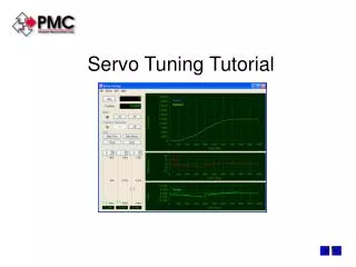
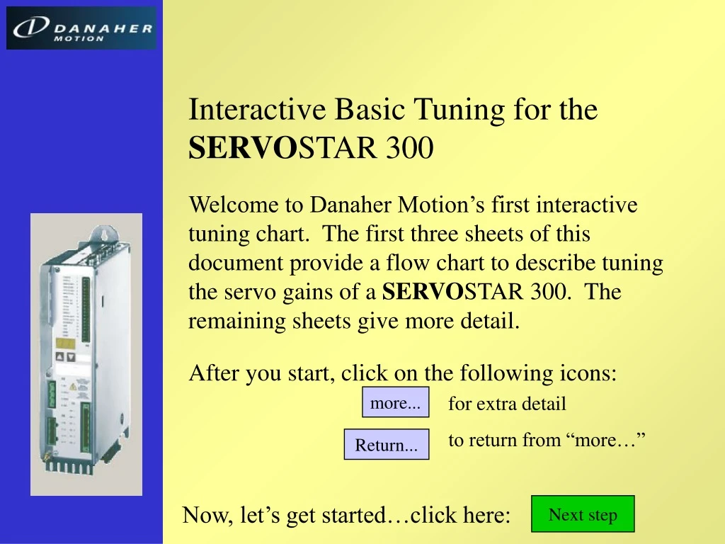
Interactive Basic Tuning for the SERVO STAR 300 Welcome to Danaher Motion’s first interactive tuning chart. The first three sheets of this document provide a flow chart to describe tuning the servo gains of a SERVO STAR 300. The remaining sheets give more detail.

E N D
Interactive Basic Tuning for the SERVOSTAR 300 Welcome to Danaher Motion’s first interactive tuning chart. The first three sheets of this document provide a flow chart to describe tuning the servo gains of a SERVOSTAR 300. The remaining sheets give more detail. After you start, click on the following icons: more... for extra detail to return from “more…” Return... Now, let’s get started…click here: Next step
Here is the velocity loop we will tune: “Ramp Limit +” “Ramp Limit -” “Speed Limit” P-gain: “KP” I-gain: “Tn” BiQuad Filter “LP Freq, HP Freq” + Limit Ramp Limit PI+ Proportional Integral (PI) Filter Current Loop Motor _ Vel Cmd Resolver/Sine Encoder Conversion Filter Filter constant: (MRESBW) Next step
After we tune the velocity loop, here is the position loop we will tune: Gain: “Ff factor” d dt Feed- forward Gain: “KP” + + + Velocity Loop Current Loop Motor Proportional Position Generator _ _ Next step
1a. Set up drive units. more... SERVOSTAR 300 Tuning STEP 1: Tune Proportional Gain 1b. Put drive in velocity mode. more... more... 1c. Turn off filters and integrator. more... 1d. Enable drive. more... 1e. Command a square wave velocity. more... 1f. Set up scope. 1g. Tune KP. more... How is it working? Works well Next step: Tune Tn Noise problem Resonance Problem Improve wiring Increase resolution Switch to sine encoder 1h. Noise Filters Stiffen machine Increase motor inertia 1i. Resonance Filters more... more...
SERVOSTAR 300 Tuning STEP 2: Tune Integral Gain Prev step: Tune KP more... 2a. Raise Integral for 5-15% overshoot. Next step: Tune Position Loop
SERVOSTAR 300 Tuning STEP 3: Tune Position Loop Prev step: Tune Tn 3a. Set mode to position loop. more... more... 3b. Set up Motion Tasks and Home drive. more... 3c. Reconfigure Scope. more... 3d. Set position loop gains low. more... 3e. Set KP to maximum level without overshoot. more... 3f. Add feed forward to improve response. Done!Click escape to end.
Step 1a • This section will give a simplified approach to setting units. The SERVOSTAR 300 has many variations of units; a few will be discussed. • Disable drive • Click on Basic Setup Main “Tree” More...
Step 1a • Select position units, normally deg, mm or “counts” Tip: This selection only affects the display of parameters on screen. It has no effect on the operation of the drive. Tip: Scale units so you will have necessary precision understanding that position entries do not support a decimal point. More...
Step 1a • Select velocity units, normally RPM, or position units per minute or per second. More...
Step 1a • Select accel units, normally ms -> VLIM, which means the time from 0 to VLIM. More...
Step 1a • Click “Position Data” • Enter the number of position units per rev • Example: for degrees, enter 360. • Set system limits on accel, velocity, etc. Return...
Step 1b • Set OPMODE = “0: Digital Speed” • Click Velocity loop from the Tree. Start by tuning the velocity loop. Return...
Step 1c • Minimize filters: LP Freq = HP Freq = 1000 • Zero integral (Tn = 0) • Set KP very low (KP 0.01) • Check top speed. • Set accel times to 1ms Tip: Turn off the filters for now…they will be used later if necessary. Tip: Setting Tn=0 makes the system proportional control to simplify tuning. Vertical axes may drift if you zero the integral. If your load will fall when the integral is zeroed, do not zero Tn. More...
Step 1c • Click Feedback from the Tree • Set Feedback Bandwidth = 300 Hz • Set Acceleration Feedforward = 1 Return...
Step 1d • Enable drive Tip: The system has very low gain. Expect it to be soft. If the system oscillates or produces any unexpected movement, remove power. Return...
Step 1e • Set up Reversing Function for Square Wave • Click Oscilloscope on tree, then Motion Service tab • Click “Parameters…” button • Set up Reversing mode from 100 to 0 RPM • For high-friction systems, avoid zero speed • Set time for 500 msec at both speeds • Click OK to return to the scope screen Tip: High inertia systems often often should be given just 25 or 50 RPM step commands. If you aren’t sure, just proceed and this will be corrected later. Tip: For linear motion, make sure V1 = -V2. More...
Start Motion • Click Motion Tab • Select Reversing mode • Click Start • If no motion is apparent, the velocity (KP) gain is probably too low. Continue to the next step. Step 1f Tip: In high friction systems, the system may not move at all because of the low gain. If that’s the case, raise KP (on the Tuning screen) in increments of 50% until you see movement. Return...
Step 1f • Set up Scope Trigger • Click Trigger Tab • Trigger Position 25%, Trigger Level 1 • Trigger Signal V_CMD More...
Step 1f • Set up Scope Channels • Click Channels Tab • Select v_cmd, v_act, and I_act as shown. • Set Time/Div. To 20 ms Return...
Tune KP • Click the Tuning Tab; Click Record button. • Raise Velocity Loop KP to maximum value without overshoot • Ensure that the current does not saturate Step 1g Tip: When the integral is turned off, the speed will often not reach top speed because of friction. In the scope shot at right, this can be seen where velocity (green) is less than command (red). Tips: A well tuned SERVOSTAR 300 driving a motor with a rigid load can respond to speed changes as fast as 2 ms without overshoot! more... Return...
Step 1h Resolution noise (for Resolver/Sine Encoder only) • If there is too much resolution noise, decrease feedback bandwidth (click “Feedback” on Tree to access). • Acceleration Feedforward (on Feedback screen) may have to be adjusted from the terminal screen, especially if bandwidth is below 200 Hz. Tip: Resolution noise sounds much like static on the radio. It has no defined pitch. Tip: Resolution noise is best solved by getting a more highly resolved feedback sensor. Consider switching to a sine encoder for the best resolution available. Resolution noise produces noisy current and noisy velocity feedback More...
Step 1h Resolution noise • Adjusting Feedback Acceleration Feedforward • See Feedback Screen Acceleration Feedback too large Acceleration Feedback right Tip: Feedback Acceleration adjusts the S300 observer. Normally it is set to 1 and only changes when resolver bandwidth is lowered below 400 Hz. Acceleration Feedback too small Return...
Step 1i Two Types of Resonance • Inertial-Reduction Instability emits an unpleasant, grinding, distorted tone. The Bode plot shows a broader frequency peak. • Tuned Resonance emits a pure tone, something like a tuning fork. The Bode plot shows a narrower frequency peak. More... More... Tuned Resonance can be narrow Bode plot of tuned resonance Return... Bode plot of inertial-reduction instability
Step 1i • Inertial-Reduction Instability • On Scope Screen, Tuning Tab • Set HP Freq >= 1000 Hz • Raise Velocity Loop KP as much as resonance allows • For more performance, try bi-quad filter More... Tip: Inertial-Reduction Instability is a problem best solved mechanically by stiffening the load, increasing the motor inertia, or reducing load inertia. Filtering techniques work, but they make it harder to get a responsive system. Small amount of ringing is okay Return...
Step 1i • Inertial-Reduction Instability: Bi-Quad Filters • On Scope Screen, Tuning Tab • Reduce LP Freq from 1000 Freq in steps of 20% • Raise Velocity Loop KP as much as resonance allows • Continue process until little overshoot is present Tip: With Inertial Reduction Instability, when you first reduce LP Freq, resonance normally worsens! Expect to reduce Kp. Below some frequency, LP Freq. will usually improve performance. However, in this example, the end performance is not clearly better than it was at the start. Small amount of ringing is okay Return...
Step 1i • Tuned Resonance: Focused Bode • Click “Parameters…” • Narrow frequency band to 50 Hz and increase points to 50 More... Open Loop: 10 dB in <25 Hz. Tip: Tuned resonance often occurs above 500 Hz, the maximum frequency of the S600 Bode plot. Return...
Step 1i • Tuned Resonance: Resolver Bandwidth • From Feedback Screen, Feedback Bandwidth=200 Hz • Raise Velocity Loop KP as much as resonance allows • Use BiQuad Filters for more improvement. More... Tip: Tuned Resonance is a problem best solved mechanically by increasing the motor inertia, or reducing load inertia. Filtering techniques work, but they make it harder to get a responsive system. Return...
Step 1i • Tuned Resonance: Bi-Quad Filters • Set HP Freq well above resonant freq. • Reduce LP Freq while maximizing Kp. Before Bi-Quad After Bi-Quad Reducing ringing and faster response! Return...
Step 2a • Tune Tn • Start with Tn ~ 3 times the settling time of Step 1 • Set Tn in “Speed” screen. Example, if settling time from Step one is 10 ms, start with Tn=30. • Lower Tn for 5% overshoot Tip: Some systems don’t need any integral gain. Integral gain provides total elimination of error at when the system comes to rest. If you don’t need this, you may want to set Tn = 0 to simplify tuning. Tip: The S300 auto scales so that velocity command and feedback may not be scaled the same. Return...
Step 3a • Set up for Position Loop • Disable drive • Set OPMODE = “8: Position Motion Tasks” • Click Motion Task Table button. Return...
Step 3b • Set up Motion Tasks • Double click on “1” on left of Motion Task Table • View Motion Task Table from main screen (see Step 3a) • Set up short move as shown below. Rapid accel, but within ability of system 500 RPM top speed Use REL ACT for simple moves. Rapid decel Next =1, repeats indefinitely This move is short, just 35 degrees. ½ second between moves Tip: Set up most aggressive move in application. If this works, the less aggressive moves should also work. More...
Home system (required for tuning) • Select Home Screen • Enable drive • Select 0 “Set Reference Point immediately” • Click Start to home. Step 3b Return...
Step 3c • Set up Scope Trigger • Set Trigger Edge Negative • Trigger Signal PSPEED More...
Step 3c • Set up Scope Channels for Position Loop • Click Channels Tab • Select PSPEED, v_act, and I_act as shown. • Adjust Time/Div. as necessary (here 10 msec) Return...
Set Position Loop gain low • Start with Ff factor = 0 • Set Position Loop KP = 0.01. Step 3d Gains are so low, peak speed is 62 RPM (500 RPM move) Tips: When in positioning mode, V_CMD is an internal signal, so it’s best to turn it off as shown here. Use PSEPEED; ignore PSPEED units. Return... Position loop gains active in OPMODE 8
Tune Position Loop gain • Start with Ff factor = 0 • Raise KV in steps of 20% to maximum level without overshoot (from Position screen). Step 3e This bump is caused by Tn being too small. More... Return...
Step 3e • Tune Position Loop gain • Continued…Eliminating the bump • To eliminate the bump, Increase Tn or Tn=0 Return...
Step 3f • Adding Velocity Feed-forward • Set Ff factor = 0.5 or 0.6 • If overshoot, reduce Position loop KP (typical 30%) Tip: A mechanically rigid system can respond quickly. This unit responds in about 15 ms with conservative margins of stability. Return...
Step 3e • Adding Acceleration Feed-forward • Restore Position KP to maximum value. • Set Ff factor to 0.8 • Set Resolver Bandwidth to > 600 Hz. • Increase GPFFT to maximize performance. • Use terminal screen and start at GPFFT = 0.2
Saturation • Saturation occurs when the current command exceeds the peak capability of the drive. This distorts data and makes tuning more difficult. If your system saturates with a square wave command, reduce command amplitude. Watch for saturation at every step of tuning! Return...