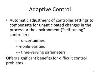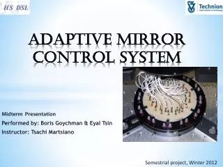
Adaptive Mirror Control System
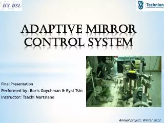
Adaptive Mirror Control System. Final Presentation Performed by: Boris Goychman & Eyal Tsin Instructor: Tsachi Martsiano. Annual project , Winter 2012. Joint project with physics faculty, deals with an adaptive mirror The mirror:

Adaptive Mirror Control System
E N D
Presentation Transcript
Adaptive Mirror Control System Final Presentation Performed by: Boris Goychman & Eyal Tsin Instructor: Tsachi Martsiano Annual project, Winter 2012
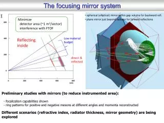
Joint project with physics faculty, deals with an adaptive mirror • The mirror: • Changes Convexity in order to correct distortions of light originated in the atmosphere • Now used for eye retina distortion corrections Background
Build a system that interfaces with a PC from one end and controls an adaptive mirror on the other. *Adaptive Mirror – contains 59 capacitors to control the shape of the mirror • Learn an approach for practical engineering. • Get familiar with FPGA, Logic Design and board design basics. Projects Goals
Part B Part A BOARD DE2 - FGPA ALTERA CHIP D2A HV S&H HV S&H System Overview DLP - USB PC DLP CHIP GUI
Microprocessor • Philips provide software and drivers, easy to implement • Need to buy one + external RAM • Board design • FPGA design • Predesigned board • Difficult to test and design with VHDL • Choosing alternative USB control – ISP • Difficult interface • Higher rate (12Mbps) Development alternatives
VHDL implementation • At least 4 FSM’s and some TBs • FPGA implementation selected • Due to availability • DLP_USB_245 • Simple FIFO – works! Devised solutions
Control a 59 capacitor adaptive mirror • 256 voltage values for each capacitor • Same controller can be used to control any other system with the same requirements • 59 inputs or less • 256 values per input • The output of the D2A will pass through • a SAMPLE & HOLD (not in the scope of part A) • and then to the mirror (not in the scope of part A) System usage & possible expansions
חבילת עדכון אחת של הקבלים במחשב 6bit capacitor 8bit voltage 00 59 ערכים HV_A 6bit capacitor 8bit voltage 00 USBtransfer 5 bit control MANAGER DLP’s FIFO FPGA’s FIFO LAST LAST D2A 8bit 6 00 8bit 8 bit control 1* 8bit 5 2 8bit 8bit 8bit 8bit 8bit Packets Split 8 bit control 8bit 8bit HV_B 5 bit control 8bit 6 00 8bit 1* 8bit 5 2 8bit 8bit 8bit FISRT FIRST * בוחר את אחד ה-HVים
General Block Diagram Ext_SD_KEY1 Ext_RESET_KEY2 Ext_START_KEY0 D2A Controller MANAGER D2A DLP_ Controller DLP245- USB D_inout[7..0] HV257 Controller SWITCH- ADG202AKN D[7..0] full wrreq RELAY-AQY274 (SC)FIFO sclr S&H-HV257 rdreq S&H-HV257 Q[7…0] empty MUX-ADG784
Designed FSM’s and coded VHDL for: • D2A Controller • DLP Controller • FIFO • HV Controller • Manager • Simulated and Emulated FSM’s for: • D2A Controller • DLP Controller • DLP Controller + FIFO • DLP Controller + FIFO + Manager • HV Controller What we have done in Part A
Tested FSM’s with: • D2A+DVM • Emulation + Leds + 7 segment • Signal Tap What we have done in Part A
Design and test the analog electric circuits : • D2A support circuit • DLP (USB) support circuit • HV support circuit • MUX, RELAY and SWITCH support circuits • 300V, +15V and -15V power supply • Integrate and test every-thing What we will do in part B