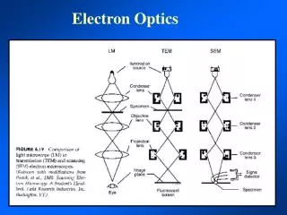
Quantrainx50 Module 3.1 Electron Optics
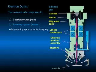
place photo here. Quantrainx50 Module 3.1 Electron Optics. 1-2011. SEM Main Components. Wehnelt cylinder or FEG unit. Electron Gun. Demagnification system. Condenser lenses. Scan generator. Scan Unit. Scan generator. Focus Unit. Objective and Stigmation lenses. Detecting Unit.

Quantrainx50 Module 3.1 Electron Optics
E N D
Presentation Transcript
place photo here Quantrainx50 Module 3.1 Electron Optics 1-2011 Confidential
SEM Main Components Wehnelt cylinder or FEG unit Electron Gun Demagnificationsystem Condenser lenses Scan generator Scan Unit Scan generator Focus Unit Objective and Stigmation lenses Detecting Unit Electron detector
SEM Main Components Electron Gun Wehneltcylinder FEG Electron Gun
Electron Gun Emitters • Tungsten filament (W) • Lanthanum Hexaboride filament (LaB6)(obsolete) • Cerium Hexaboride (CeB6) • Field emission filament (FEG)
Electron Gun Animation * * Video courtesy of Oxford Instruments
ą ip do specimen Electron Source Properties • Current density (brightness) • Emission current • Stability of source • Lifetime of filament • Design of electron source assembly • Ease of operation • Costs involved
Emission Area For Tungsten (W) Filament heating supply Filament Wehnelt cap Cross-over plane 70 A Anode High voltage supply (200 v- 30 kV)
Bias on Wehnelt Cap Optimum bias voltage Low bias voltage High bias voltage Equipotential lines of the Voltage Field 0 0 0 + + + Noemission High emission large spot Sufficient emission small spot
Emission : Autobias control Bias 255 ……………………………….. Bias 1 110µA 90µA 1 kV30 kV Autobias keeps emission between 90-110 µA for all kV 9
W Filament Saturation Saturation point emission current False peak / Misalignment filament current
XL Schottky FEG Theory o o o o o o o o o o • The Boersch Effect • A) Perfect beam: no interactions • B) Random beam: one dimension • C) Random beam: two dimensions • It is actually three dimensional o o o o o o o o o o o o o o o o o o A B C
XL Schottky FEG Theory • The Lateral Effect • lateral trajectory displacement • This effect results in a larger final spot • The diameter of the circle of confusion due to this effect. o o o o o o o o oo o o
Lens Defects optical axis Aperture image plane Spherical aberration Chromatic aberration Diffraction
Spherical Aberrations • Electrons entering into a lens at different points get focused at different points Disc of Least Confusion
Chromatic Aberrations • Electrons of differing energies will be focused at different places Disc of Least Confusion
Diffraction • The wave nature of electrons cause diffraction limitations
XL Schottky FEG Theory • Design Limitations • Longer electron-electron interaction times and smaller electron-electron distances lead to higher statistical aberrations at low KV • Chromatic aberration is more dominant at low voltages.
XL Schottky FEG Theory • Innovative solutions to reduce design limitations • A Coulomb tube designed into the column to reduce aberrations and interactions by keeping a high beam energy in the tube • Effective aperturing of the beam to remove those electrons not contributing to the probe
FEG Column Principle Diagram C1 10KV Drift Space (Coulomb Tube) Gun Alignment Coils C2 Objective Aperture Scan Coils Objective Lens
Emission Area for FEG Filament heating supply Extractor system C1 static lens 150 A Anode High voltage supply (200 v- 30 KV)
Schottky Gun Design • Fil = Filament current input (2.4 Ampere) • S = Suppressor (-500V) • E = Extractor (+5000V) • C1 = Electrostatic Condenser lens Fil S E E C1
Schottky Tip design • M = Tip module • W = Welded tungsten Tip • Fil = Tungsten wire filament • T = Sharpened Tip • Zr = Zirconium reservoir M T W Fil Zr
FEG Startup Steps • Warmstart / Coldstart • Gun conditioning
Beam Menu Final operation status
FEG Column Double condenser lens • Extraction voltage changes not necessary, beam current is set by condenser lenses • C1 is electrostatic • C2 is electromagnetic • Variable lens strengths: A = high beam current mode B = low beam current mode • Final beam energy 30keV down to 200eV C1 C2 A B
FEG Column Double Condenser Lens • Extraction voltage changes not necessary, beam current is set by condenser lenses • C1 is electrostatic • C2 is electromagnetic • Variable lens strengths: A = high beam current mode B = low beam current mode • Final beam energy 30keV down to 200eV C1 Internal Spray Aperture C2 A B
FEG Column • Different paths for low and high beam current conditions through the coulomb tube, but common path to objective C1 C2 Deceleration Lens Aperture Small Spot Large Spot
SEM Main Components Electron Gun Wehnelt cylinder Demagnification system Condenser lenses Demagnificationsystem Scan Unit Scan generator
L L Magnification M=L/l l ***-important
Scan Size Vs. Magnification • Low Mag. • Med Mag. • Hi Mag.
Magnifying Your Sample on Quantax50 l L L _ M= l
Low Magnification Scan Here Display Here
Intermediate Magnification Scan Here Display Here
Higher Magnification Scan Here Display Here
The viewed area (L) is fixed The smaller the area scanned on the sample results in higher viewed magnification Scan Size Vs. Magnification
The Crossover point on the Beam is of a Finite Size I = BeamCurrent D=Spot Size ą = Measurement of the ‘cone’
Current Density • Current Density remains constant through the optical path of the electron beam 4 X IAmps β = π 2 a ( ) Cm Steradians X d o X
Current Density (remove constants) • Current and Spot size are directly proportional IAmps β = 2 ( ) Cm d o
Resolution The resolution of the microscope is a measure of the smallest separation that can be distinguished in the image unresolved resolved
The Diameter of the Electron Beam Must Be Smaller Than the Feature to Be Resolved
The Electron Beam Scans From Left to Right • There can be from 512 to 4096 scan lines, at all magnifications
The Electron Beam Spot Size Must Be Smaller Than the Features Being Resolved • The ideal spot size
Too Large of Spot Size Looks Out of Focus • Too big of spot size creates an out of focus image