Download
1 / 25
250 likes | 402 Views
A NANOSATELLITE MISSION TO ASSESS SOLAR SAIL PERFORMANCE IN LEO. Kieran A. Carroll, Gedex Inc. Henry Spencer, SP Systems Robert E. Zee, Space Flight Laboratory George Vukovich, Canadian Space Agency. Goals of This Presentation. To introduce publicly the CanX-9 solar sail technology mission

E N D
A NANOSATELLITE MISSION TO ASSESS SOLAR SAIL PERFORMANCE IN LEO Kieran A. Carroll, Gedex Inc. Henry Spencer, SP Systems Robert E. Zee, Space Flight Laboratory George Vukovich, Canadian Space Agency
Goals of This Presentation • To introduce publicly the CanX-9 solar sail technology mission • To convey a sense of the design approach that has been followed. • To provide a starting point for coordinating this mission’s objectives with those of others who are working to mature solar sailing technology, e.g.: • IKAROS • Nanosail-D2 • Lightsail-1 • Cubesail A Nanosatellite Mission to Asses Solar Sailing Performance in LEO International Solar Sail Symposium 2010, New York
Background: History of Solar Sailing in Canada • 1978: Modi & Van Der Ha orbital dynamics papers (UBC) A Nanosatellite Mission to Asses Solar Sailing Performance in LEO International Solar Sail Symposium 2010, New York
Background: History of Solar Sailing in Canada • 1978: Modi & Van Der Ha papers • 1988-92: Canadian Solar Sail Project (CSSP) • CCQJC Race to Mars • Canadian Space Society • University of Toronto Institute for Aerospace Studies (UTIAS) • (Team members included Carroll and Spencer) A Nanosatellite Mission to Asses Solar Sailing Performance in LEO International Solar Sail Symposium 2010, New York
CSSP Initial Design Concept • Novel non-spinner • Hexagonal planform • “Venetian blind” sail vanes: • Stowed rolled-up • Deployed and actuated by cables • Compressive booms, each 60 m long • 500 kg, 10,000 m2 • Smallsat-class • Ariane 4 launch to escape A Nanosatellite Mission to Asses Solar Sailing Performance in LEO International Solar Sail Symposium 2010, New York
CSSP Eventual Preliminary Design • Novel spinner • “Pinwheel” configuration • 30 vanes, each 30 x 0.5 m, stowed and deployed roller-blind fashion • 3 of the vanes with adjustable angle of attack for spin-rate control • Precess spin vector (and hence sail pointing) direction via shifting mass center • 25 kg, 500 m2 • Microsat-class • Scout or Pegasus launch to escape A Nanosatellite Mission to Asses Solar Sailing Performance in LEO International Solar Sail Symposium 2010, New York
Background: History of Solar Sailing in Canada • 1978: Modi & Van Der Ha papers • 1988-92: Canadian Solar Sail Project (CSSP) • CCQJC Race to Mars • Canadian Space Society • University of Toronto Institute for Aerospace Studies (UTIAS) • Team members included Carroll and Spencer A Nanosatellite Mission to Asses Solar Sailing Performance in LEO International Solar Sail Symposium 2010, New York
Background: History of Solar Sailing in Canada • 1978: Modi & Van Der Ha papers • 1988-92: CSSP • 1990s: KAC @ Dynacon • Polar Relay Satellite (POLARES) concept study: • ~100 kg polesitter for north pole region data backhaul • With SPAR, for Canadian DND • Heliogyro-like, with ~25 kg despun comms payload • (Independently conceived pole-sitter concept) • Several solar sailing conference papers • Solar sail applications study for CSA • Supervised M.A.Sc. magnetosphere mission study A Nanosatellite Mission to Asses Solar Sailing Performance in LEO International Solar Sail Symposium 2010, New York
Background: History of Solar Sailing in Canada • 1978: Modi & Van Der Ha papers • 1988-92: CSSP • 1990s: KAC Dynacon solar sail activities • 1996-2003: MOST microsat mission for CSA • Learned how to design and build microsats • UTIAS Space Flight Laboratory founded, major subcontractor to Dynacon A Nanosatellite Mission to Asses Solar Sailing Performance in LEO International Solar Sail Symposium 2010, New York
Background: History of Solar Sailing in Canada • 1978: Modi & Van Der Ha papers • 1988-92: CSSP • 1990s: KAC Dynacon solar sail activities • 1996-2003: MOST microsat mission • 2000-2010: • SFL nanosats • CanX program A Nanosatellite Mission to Asses Solar Sailing Performance in LEO International Solar Sail Symposium 2010, New York
SFL’s CanX Program • Canadian Advanced Nanospace eXperiment program • Developing/flying significantly capable nanosats (1-10+ kg) • Providing nanosat launch services via XPOD launcher i/f • Current missions use the Generic Nanosat Bus (GNB) platform (20x20x20 cm) A Nanosatellite Mission to Asses Solar Sailing Performance in LEO International Solar Sail Symposium 2010, New York
CanX-9 Mission Concept • Fly a solar sail technology demonstrator using SFL nanosat technology • Seek a partner to provide the solar sail subsystem • Demonstrate directed solar sail thrusting • Fly as a secondary payload in LEO • Expected total cost: <<$10M A Nanosatellite Mission to Asses Solar Sailing Performance in LEO International Solar Sail Symposium 2010, New York
CanX-9 Programmatics • Initial preliminary design carried out at SFL • Partners include: • Technology P.I. and Team • Source of mission requirements • Processes technology payload data to accomplish tech demo • Membership drawn from participating organizations • SFL • Mission prime contractor • Bus and XPOD supplier • Arrange launch • L’Garde • Provision of solar sail subsystem • CSA • Supported initial design study • Considering funding the mission A Nanosatellite Mission to Asses Solar Sailing Performance in LEO International Solar Sail Symposium 2010, New York
Mission Objectives • Address issues impeding the use of solar sailing in operational missions • Qualitative: • Demonstrate significant orbit changes via active solar sailing • Flight-test inflatable-boom square-sail technology • Quantitative: • Determine sail reflectivity to within 1% by measuring orbit changes • Determine changes in SRP force and torque with time A Nanosatellite Mission to Asses Solar Sailing Performance in LEO International Solar Sail Symposium 2010, New York
Some Design Drivers/Issues • Lack of available SRP torque actuators drives preference for low Earth orbit, thus 1000 km upper altitude constraint: • Strong Earth magnetic field in LEO advantageous • Also reduces power for comms • Atmospheric force/torque effects provide a 700 km (TBC) lower altitude constraint: • Issue: magnitude of these forces and torques difficult to analyze in advance (“area of active research”) • Will depend somewhat unpredictably on launch timing and Solar cycle phasing • Cost drives use of nanosat development approach: • Thus COTS EEE parts used • Radiation TID constraint drives altitude limit to below 1000 km or above GEO • Cost drives use of secondary-payload launch: • Secondary launch availability constrains orbit availability and launch timing • Sun-synchronous orbit preferred due to availability of launches, and resulting slowly-varying Sun-phase angle which simplifies some aspects of mission and system design A Nanosatellite Mission to Asses Solar Sailing Performance in LEO International Solar Sail Symposium 2010, New York
Mission and System Design • Secondary payload launch using XPOD • Sun-synchronous orbit, 700-1000 km altitude • Sail area 25 m2 , mass <14 kg, mass/area ratio: <560 grams/m2 • Payloads for measuring orbit changes to determine reflectivity to within 1% in 1 month • Use SFL UHF-up/S-band-down ground station • Quick-look payload data evaluation capability to support day-to-day mission planning • Non-real-time analysis of payload data to accurately estimate model parameters for solar radiation pressure and atmospheric forces A Nanosatellite Mission to Asses Solar Sailing Performance in LEO International Solar Sail Symposium 2010, New York
XPOD Duo Launcher I/F • Developed for CanX-4/5 mission • Capacity: • Designed to carry a dual-GNB bus • 20x20x40 cm • 14 kg • Size (w/o spacecraft): • 47 x 47 x 52 cm • 10 kg • Customizable • Relatively softer ride • Can accommodate fixed appendages A Nanosatellite Mission to Asses Solar Sailing Performance in LEO International Solar Sail Symposium 2010, New York
Payloads • Solar sail subsystem • Inflatable-boom square sail • To be provided by L’Garde • Cameras • To provide deployment video • Boom-mounted to get far enough above sail plane for a good view • GPS receiver • To provide low-frequency data on orbit changes • Flight heritage from CanX-2 • 3-axis accelerometer • To provide high-frequency data on orbit changes • Performance requirement: 10-7 m/s2 RMS accuracy at 0.01 Hz • Total mass ~ 3 kg A Nanosatellite Mission to Asses Solar Sailing Performance in LEO International Solar Sail Symposium 2010, New York
Satellite Design • Bus • Thermal • OBC • Radios • Power • Structure • ACS • Payloads • Solar Sail subsystem • Cameras + boom • GPS receiver • Accelerometer Per existing GNB designs Significantly modified GNB designs New designs A Nanosatellite Mission to Asses Solar Sailing Performance in LEO International Solar Sail Symposium 2010, New York
CanX-9 Bus • To be developed by SFL • Mass ~ 12.5 kg • Including sail support structure • Including 25% margin • 20x20x40 cm main structure: • 20x20x20 cm lower bus • 20x20x15 cm upper bus • Sail stowed in 20x20x5 cm “sail-box” layer between lower and upper bus sections A Nanosatellite Mission to Asses Solar Sailing Performance in LEO International Solar Sail Symposium 2010, New York
CanX-9 With Sail Deployed A Nanosatellite Mission to Asses Solar Sailing Performance in LEO International Solar Sail Symposium 2010, New York
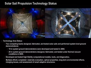
Solar Sail Subsystem • To be supplied by L’Garde • Miniaturized version of L’Garde 20m ground system demonstrator: • Square sail, 5.5m across flats, 25 m2 area • Four 4.1m inflatable booms, thermally rigidized • Stripe-net support • Mass ~ 1.5 kg (including 20% margin): • Sail: 0.2 kg • Booms: 0.3 kg • Deployment gear: 1.0 kg A Nanosatellite Mission to Asses Solar Sailing Performance in LEO International Solar Sail Symposium 2010, New York
Attitude Control Subsystem • Zero-momentum, 3-axis stabilized to 1 degree accuracy • Sensors: • 9 Sun sensors on bus faces • 3-axis magnetometer on fixed boom • 3 angular rate sensors • Actuators: • 3 magnetic torque rods • 3 reaction wheels • All hardware and ACS software has CanX flight heritage • Mass ~ 1.75 kg, power ~ 4W A Nanosatellite Mission to Asses Solar Sailing Performance in LEO International Solar Sail Symposium 2010, New York
Power Loads by Mode: Safe-Hold: 2 W Detumble:2.5 W Pre-deployment: 6 W Deployment: 29 W Post-deployment: 9 W Sail boom heaters and valves: 14 W, for 1-2 orbits around deployment time Payload power: 2-3 W orbit-average Transmitter power: 5 W, 100% duty cycle when sending down deployment video Power Supply 45 pairs of ~ 27% efficiency (BOL) triple-junction solar cells 27 pairs body-mounted 18 pairs wing-mounted Each with 920 mW max power generating capacity at worst-case-hot temperature 2x 20 W-hr Li-ion batteries Mass: ~ 2.25 kg Power Subsystem A Nanosatellite Mission to Asses Solar Sailing Performance in LEO International Solar Sail Symposium 2010, New York
Thermal Subsystem • Mostly passive (careful choice of coatings) • Spot-heaters on some parts (battery, accelerometer) • Large heaters in sail booms, to raise their temperature prior to deployment • Boom-to-bus insulation to keep booms from cooling too quickly during deployment • Choice of boom epoxy, to have a glass transition temperature to match bus worst-case-hot temperature • Analysis of Solar radiation incident on the bus versus sail orientation with respect to the Sun: • Maximum reflected-Sunlight bus heating level of ~ 12W (versus direct-incidence Sunlight ~ 35W) • Analysis of sail heating radiatively coupling into bus heating: • Face-on to the Sun, the sail temperature can reach 150 C • This effect is largest when the reflected Sunlight effect is least A Nanosatellite Mission to Asses Solar Sailing Performance in LEO International Solar Sail Symposium 2010, New York