Download
1 / 45
470 likes | 1.38k Views
U.S. Department of the Interior Bureau of Reclamation. WinFlume for Experts An Interactive Working Session on the Use of WinFlume Design and calibration of long-throated flumes and broad-crested weirs. Tony L. Wahl Water Resources Research Laboratory Denver, Colorado

E N D
U.S. Department of the InteriorBureau of Reclamation WinFlume for Experts An Interactive Working Session on the Use of WinFlume Design and calibration of long-throated flumes and broad-crested weirs Tony L. Wahl Water Resources Research LaboratoryDenver, Colorado Albert J. Clemmens, USDA-ARS Marinus G. Bos, ILRI John A. Replogle, USDA-ARS Retired
Traditional Critical-Flow Devices • Traditional critical-flow devices have curved,three-dimensional flow fields in the control section • Parshall flumes, cutthroat flumes, H-flumes, etc. • V-notch weirs, Cipoletti weirs, rectangular weirs • Traditional broad-crested weirs lacked an adequate transition and had 3D flow and/ornon-hydrostatic pressure distributions at the control section • All such devices require laboratory calibration
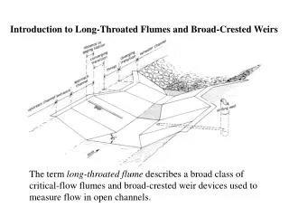
Modern Long-Throated Flumesand Broad-Crested Weirs • Converging transition and length of throat or sill createone-dimensional flow at the control section • Long-throated means long enough to eliminate lateral and vertical contraction of the flow at the critical section,so streamlines are essentially parallel • Can be calibrated using well-established hydraulic theory • No laboratory testing needed • Accurate calibration of as-built structures is possible • Custom designs can be easily calibrated • Calculations are iterative • Computer models that do the calculations have made long-throated flumes reasonable to implement in recent years
Submergence of Flumes and Weirs • Sharp-crested weirs • NO SUBMERGENCEALLOWED • Parshall flume • Some submergence allowed • Long-throated flume and broad-crested weir • Most submergence allowed • Lowest head loss
Constructability Range of Flows to be Measured Throat Section Shape Selection
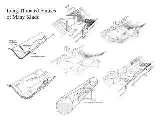
Typical Flume/Weir Configurations • Sill in a concrete-lined canal • Rectangular-throated flumes for earthen canals • Triangular-throated flumes for natural channels • Flumes in circular pipes • Portable and temporary flumes
Calibrating an Existing Structure • Define geometry of canal and flume • Provide hydraulic data and other properties • Construction material • Tailwater conditions • Generate output • Rating tables and curves • Curve-fit equation for data logger • Wall gage data and/or plot
Designing a New Structure • Define canal geometry and initial flume control section • Provide hydraulic data, canal/flume properties, design requirements • Construction material • Tailwater conditions • Water level measurement method and required flow measurement accuracy • Required freeboard in upstream channel • Size and set control section • Refine lengths of flume components • Generate output
Principal Design Issues • Site • Uniform, fully-developed flow conditions approaching structure so that hydraulic theory is applicable • Flume control section • Ensure that flume is not submerged by tailwater (contraction must be enough to force critical depth) • Ensure structure ponds water deep enough to stabilize upstream water surface for accurate measurement (Fr < 0.5) • Ensure that flume does not create a “lack of freeboard” problem at maximum flow • Ensure that contraction produces enough head to make an accurate flow measurement • Component lengths must meet “long-throated” criteria
Lengths of Flume Components • Throat section length, L 0.07<H1/L<0.7 for ±2% uncertainty 0.05<H1/L<1.0 for ±4% uncertainty • Floor and sidewalls of converging transition 2.5 to 4.5:1 transition slope • Diverging transition No flatter than 10:1 • Gaging station location (approach channel length) > H1 upstream of start of converging transition (2 to 3) * H1max from start of throat
Flume Design & Selection • Pre-computed flume designs can be chosen using tables provided in several references • Water Measurement Manual • Water Measurement with Flumes & Weirs • Designs can be developed using the WinFlume computer program • Allows for customization • Provides best rating table accuracy • Simplifies checking of design
Water Resources Research Laboratory Denver, Colorado U.S. Water Conservation Laboratory Phoenix, Arizona International Institute for Land Reclamation & Improvement Wageningen, The Netherlands WinFlumeSOFTWARE FOR THE DESIGN AND CALIBRATION OF LONG-THROATED FLUMES AND BROAD-CRESTED WEIRS
HOW TO OBTAIN WINFLUME • WinFlume is available on the World Wide Web at: http://www.usbr.gov/pmts/hydraulics_lab/winflume • The program operates on all Windows-based computers This work has been funded by the U.S. Bureau of Reclamation’s Water Conservation Field Services Program.
Design Examples • Calibrating an existing structure • Entering data • Generating rating tables, equations, wall gages • Trial and error design • Design using WinFlume’s automated tools • Designing a flume with tight constraints
Calibrate This Structure… Channel: Trapezoidal, 0.3 m base width, 1:1 side slopes, 0.55 m deep Sill Height: 0.3 m Approach Length: 0.2 m Upstream Ramp: 3:1 slope (0.9 m long) Throat Length: 0.35 m Construction Material: Smooth concrete Tailwater Conditions: Normal Depth Manning’s n = 0.015Sbed = 0.00050 (0.5 m/km) Discharge Range: 0.05 to 0.15 m3/s
Design by Trial… • Find appropriate sill height given that: • We must maintain freeboard of at least 20% of head on weir • We will measure upstream head with a staff gage in a stilling well • Allowable measurement errors are 5% at maximum flow and 8% at minimum flow p1=0.4 m overtops upstream channel p1=0.35 m violates freeboard requirement p1=0.3 m is not sufficiently accurate at Qmin p1=0.25 m is acceptable p1=0.2 m is submerged at Qmax
WinFlume’s Design Module • User chooses a method of contraction change and an increment at which to evaluate designs (e.g. evaluate designs at sill height increments of 0.1 ft). • WinFlume brackets the range of possible designs by evaluating flume performance at the maximum design flow: • The maximum possible throat-section contraction is that needed to produce a maximum upstream water level equal to channel depth. • The minimum contraction is that which produces an upstream Froude number of 0.5 at maximum discharge, and an upstream water level that is at least as high as the downstream tailwater at maximum discharge. • WinFlume builds and evaluates designs of “virtual” flumes between the lower and upper contraction limits at the interval specified by the user.
Design Module Results • Results are presented to the user, who may choose to accept any one of the designs or discard the results. • Only designs meeting the four primary design criteria (freeboard, Froude number, no submergence at minimum and maximum flow) are presented, unless there are no acceptable designs. • Designs that meet the four primary criteria, but do not meet measurement precision requirements may be improved by specifying a better water level measurement method. • Acceptable designs that have minimum head loss, maximum head loss, intermediate head loss, or head loss matching the bed drop at the site are highlighted in the output • The user can choose the design that best meets their needs. A throat section with more contraction than the minimum required will provide protection against excessive submergence of the structure if tailwater levels prove to be higher than expected.
If An Acceptable Design Is Not Found On The First Trial • If the contraction increment is too large, or if design criteria are too limiting, no acceptable design will be found. Is an acceptable design possible? • WinFlume searches for two adjacent designs for which the unsatisfied criteria in each design are satisfied in the adjacent design. • An acceptable design may exist between those two designs • Analysis is repeated using a smaller increment of contraction change within that range. • If no region of acceptable designs is found, then all results are presented to the user, with suggestions for how to relax the design criteria or change the initial design so that an acceptable design can be found.
Results from Design Module… • Vary the sill height in increments of 0.05 m • Sill heights between 0.24 m and 0.333 m are acceptable • Sill heights above 0.286 m do not meet accuracy requirement at minimum flow • Could be fixed by using more accurate head measurement method
Now Let’s Make Things Tougher(example 5.6.6 from Water Measurement with Flumes & Weirs) • Canal operators insist on using a staff gage in the canal, and want to meet accuracy requirements as before: ± 5% at Qmax ± 8% at Qmin • Changing the sill height does not work • Try raising the entire control section as a unit, making the throat identical to the canal shape (0.3 m base width) • Sill heights from 0.153 m to 0.189 m will work • This style of structure is more difficult to build
Tougher Yet… • Canal depth is now 0.5 m ! • Freeboard problem and submergence problem at Qmax overlap one another • What can we do? Change throat shape, but how? • Main problem right now is freeboard vs. submergence…don’t worry about accuracy yet • Wider, shallower flow in the throat will… • Reduce upstream head, thereby increasing freeboard • Require less head loss (DH is proportional to H1) • Reduces freeboard requirement (20% of head)
Let’s Try It… • Choose a trial sill height and let WinFlume determine the throat width • A few trials show that this solves the freeboard vs. submergence problem, but there is no solution to the accuracy problem • Throat width must be 0.36 m or less to satisfy accuracy requirements, but then freeboard is a problem • Note that throat length can affect evaluation of accuracy criteria. If H1/L<0.07 orH1/L > 0.7, WinFlume penalizes accuracy
One More Thing to Try… • A diverging transition would reduce required head loss and might give us more design freedom • Go back to the design that used the 0.3 m base width. Add a 6:1 downstream ramp and try varying the throat section elevation again • A sill height of 0.14 m (±3 mm!) is acceptable
Design Example Summary • Essential tradeoffs demonstrated • Freeboard vs. submergence at Qmax is most common issue, and sometimes accuracy is also a factor • Sometimes Froude number will control rather than submergence • Submergence at Qmin is very rarely a problem • Changing throat section shape is sometimes necessary and requires user intervention • Refinement of flume component lengths can come after throat section is sized and set (but throat length sometimes affects accuracy, so keep an eye on it) • Designs for existing canals are often tightly constrained • Flumes for new canals are much easier – required head loss can be incorporated into canal design
Special Topics • Non-symmetric sections • Analyzing “imperfect” as-built flumes • Cross-slope of a “flat” sill • Longitudinal slope of sill • Warning messages regarding converging transition length • Flumes with compound control sections
Non-Symmetric Sections • Not an ideal situation, but tolerable if Z1 and Z2 are not dramatically different • Model with a symmetric section using Z=(Z1+Z2)/2 • Mathematically, this produces correct cross-sectional area and top width, but wrong wetted perimeter • Slightly distorts tailwater and frictional head loss calculations 1 1 Z2 Z1 1 Z
Analyzing Flume with Cross-Slope • Cross-slope of a “flat” sill • Determine “average” sill height and model as a flat sill at that sill height • Or, model with a complex shape (a V-section in bottom of throat) with cross slope that is double actual slope.
Flume with Longitudinal Slope • Most difficult problem to correct for • Slope moves critical section toward a zone with streamline curvature • Increases discharge coefficient • If sloped uphill in the flow direction, reference head measurement to downstream end of sill • If sloped downhill, reference head to leading edge of the sill • If slope is 3° or more…REPAIR THE FLUME
Warning Messages Regarding Converging Section Length • 2.5:1 to 4.5:1 transition is desired • Steeper than 2.5:1 causes flow separation at start of throat…affects transition to critical depth • Flatter than 4.5:1 yields uneconomical structure and increases friction loss between gage and control section • WinFlume evaluates: • Vertical contraction of flow due to raised sill • Horizontal contraction of flow due to narrowed throat • Warning messages can be difficult to overcome when aspect ratio of approach and throat sections are dramatically different • Better to make the converging transition too long rather than too short. (Too short could cause flow separation at entrance to throat and affect flow at critical section)
Qmax Qmin y1max y1min Length of Converging Transition- Throat Section Narrow at Base - • Range of acceptable lengths is 2.5 to 4.5 times the maximum of the “contraction distances” shown • Evaluated separately at Qmin and Qmax • Large horizontal contraction at the sill elevation requires long converging section • Horizontal contraction at sill is large if base width is small or zero (V-shaped)
Flumes with V-Shaped or Compound Control Sections • Often difficult to obtain “acceptable” length of converging transition, or acceptable length seems unreasonably long • Better to make the converging transition too long rather than too short. (Too short would cause flow separation at entrance to throat and affect flow at critical section) • Compound shapes have reduced accuracy in transition zone from inner shape to outer shape • First, consider a triangular shape when Qmax/Qmin is large
Qmax Qmin y1min Length of Converging Transition- Rectangular Throat - • Controlling (maximum) contraction length may be dramatically different at minimum and maximum flow • Can lead to “contradictory” warning messages that converging section is both too short at Qmax (more abrupt than 2.5:1) and too long at Qmin (flatter than 4.5:1) • Solutions: • Choose the longer recommended length. Gradual transition is best • Use a trapezoidal throat (similar to approach channel shape) • Use different transition lengths for sides and floor y1max D:\WinFlume\Workshops\Exercise Flumes\Converging Section Length Paradox Example.Flm