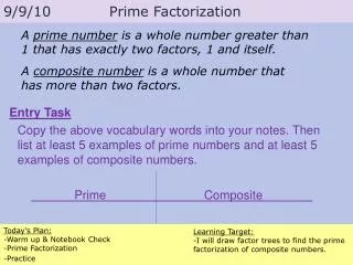
Notebook Check
Notebook Check. Tsjellum van der Stok. State Diagram. This page shows the proposed State diagram that will be implemented. Hysteresis is shown. Temperature Progression. This is an exaggerated temperature range I sketched out after speaking with Professor St. Dennis. Transistor Relay Switch.


Notebook Check
E N D
Presentation Transcript
Notebook Check Tsjellum van der Stok
State Diagram This page shows the proposed State diagram that will be implemented. Hysteresis is shown.
Temperature Progression This is an exaggerated temperature range I sketched out after speaking with Professor St. Dennis
Transistor Relay Switch Simple Transistor circuit, allowing a low voltage and low current microcontroller/USB-6008/PLC to operate the relay. Note the base resistor calculation
MOSFET relay switch MOSFET relay control circuit, another option to allow a micro or other to control the relays. Note the 100 ohm resistor to prevent short circuit reset in micro when FET is first turned on. MOSFET gate capacitance may source too much current when switched, maybe I was not sleeping in class, Andre
Modine Heater Circuit Modine heater control circuit, just from the manual override control board. Researching the serial number yielded information on the mechanical thermostat, which requires to electronic intervention
Vent Motor Control Initial Motor control schematic, followed by further detail after reading the Wadsworth user manual
Vent Motor Schematic Photocopy of current vent motor control schematic, hopefully this will shed light on the inoperability of the side vent motor
Aspirator This photocopy displays the mechanical layout and wiring details of the Wadsworth temperature sensor. This ought to aid in the integration of these sensors