i-tech.si
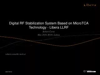
Digital RF Stabilization System Based on MicroTCA Technology - Libera LLRF. Robert Černe May 2010, RT10, Lisboa robert.cerne@i-tech.si. www.i-tech.si. Outline. Introduction Hardware overview Digital signal processing Software architecture LLRF application. www.i-tech.si.

i-tech.si
E N D
Presentation Transcript
Digital RF Stabilization System Based on MicroTCA Technology - Libera LLRF Robert Černe May 2010, RT10, Lisboa robert.cerne@i-tech.si www.i-tech.si
Outline • Introduction • Hardware overview • Digital signal processing • Software architecture • LLRF application www.i-tech.si
Introduction 1/2: Instrumentation Technologies and the Libera brand • Provider of state-of-the-art Libera family instrumentation systems. • Instrumentation systems are used for diagnostics and beam stabilization at particle accelerators. • All-in-one instruments cover analog and real-time digital signal processing and high level software. www.i-tech.si
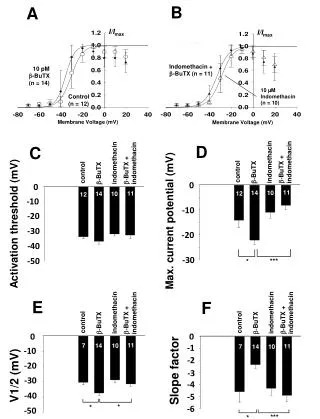
Introduction 2/2: LLRF application and key requirements • LLRF application: • Low Level RF (LLRF) systems are responsible for precise control of RF fields in the accelerating structures and use feed-back or/and feed-forward techniques to achieve this. • Key requirements: • 36 RF input channels. • Low amplitude and phase noise of the LLRF receiver and LLRF transmitter. • Distributed digital signal processing. • Low latency data transfer between FPGAs (< 100 ns). • High data throughput between FPGA and CPU. • Small form factor. • Generic design to support reuse of developed hardware for development of new instruments. www.i-tech.si
Hardware Overview 1/7: Technologies • Based on MicroTCA/AMC standards. • Based on IPMI board management. • Intel dual core COM Express computing module. • PCIe over backplane and cable. • Gigabit ethernet. • Low latency LVDS links. • Distributed processing on Xilinx Virtex 5 FPGAs. • Distributed acquisition circular buffers (DDR2RAMs). www.i-tech.si
Hardware Overview 2/7: Architecture • Chassis is designed to fit into 19 inch rack and has 2U height. • Integrated power supply module that produces12 V payload power. • Chassis and backplane can accept up to eight AMC modules (4x double width and 4x single width; all mid-size). • ICB board in non AMC slot at the top on the left. • Cooling is performed by two replaceable fan modules, which produce horizontal air flow. www.i-tech.si
Hardware Overview 3/7: Interconnection Board (ICB) • Implements MCH functions and acts as a COM Express carrier board. • Power distribution. • High throughput PCIe switch fabric. • Distribution of switch fabric clock. • IPMI management of AMC modules. • Integrated COM Express module with powerful CPU. • FPGA for configuration and control of ICB hardware. • Interfaces: JTAG, RS232, host USB, management Ethernet, 2xPCIe, 2x LXI, DVI, USB and 2xGbE. www.i-tech.si
Hardware Overview 4/7: LLRF receiver AMC module • Consists of digital and RF PCBs. • 9 RF input channels, LO (Local Oscilator) input and calibration input. • Down conversion technique used. • 9 x 16 bit ADCs (up to 130 MS/s), raw acquisitions (DDR RAM up to 8 Gbits) • Virtex 5 FPGA . • ARM processor with IPMI support. • DMA implemented in FPGA. • PCIe endpoint implemented in FPGA. • 8x PCIe link to the card edge connector. • SerDes transmitters implemented in FPGA. • Dedicated low latency LVDS links to the card edge connector. www.i-tech.si
Hardware Overview 5/7: LLRF transmitter AMC module • Consists of digital and RF PCBs. • 2 RF output channels, 2 RF input channels abd LO input. • Up/Down conversion technique used. • 2 x 14 bit double DACs (up to 260 MS/s), 2x 16 bit ADCs raw acquisitions (DDR RAM up to 8 Gbits) • Virtex 5 FPGA . • ARM processor with IPMI support. • DMA implemented in FPGA. • PCIe endpoint implemented in FPGA. • 4x PCIe link to the card edge connector. • SerDes receivers implemented in FPGA. • Dedicated low latency LVDS links to the card edge connector. www.i-tech.si
Hardware Overview 6/7: Timing AMC module • Consists of digital and RF PCBs. • MO (Master Oscillator) input. • LO (Local Oscillator) generation and output. • Sampling clock generation and distribution to AMC modules. • Interlock input and output. • 2x trigger input and distribution to AMC modules. • ARM processor with IPMI support. • Lattice FPGA . • PCIe endpoint implemented in FPGA. • 1x PCIe link to the card edge connector. www.i-tech.si
Hardware Overview 7/7: Backplane • 3.3 V and 12 V payload power connections from ICB to all AMC modules. • Digital lines for JTAG communication between ICB and each AMC module. • Digital lines for I2Ccommunication between ICB and each AMC module. • Differential lines between ICB and each AMC module for USB communication. • Differential lines between ICB and each AMC module used for PCIe lanes and PCIeclock. • Differential lines between Timing AMC module andeach AMC module used forsampling clock distribution. • Two digital lines between Timing AMC module and each AMC module for interlock information transfer. • Differential lines between LLRF transmitter and each LLRF receiver. www.i-tech.si
Signal Processing Overview 1/2: Control loops • Low latency cavity field control loop • Scaling and phase rotation of probe signals • Partial / global vector sum calculation • Set-point signal generation • Feed forward signal generation • Pulse shaping (during fill time, flat top ) • Feed-back / feed-forward control algorithms • Drive signal generation • Interlock triggering based on signal power threshold www.i-tech.si
Signal Processing Overview 2/2: Signal acquisition www.i-tech.si
Software Overview: Software architecture www.i-tech.si
LLRF Application Overview 1/3: Functions • Libera LLRF system operation (state transitions, parameter setting, interlock control). • Signal monitoring. • Different RF diagnostics, calibration and compensation algorithms. www.i-tech.si
LLRF Application Overview 2/3: Freq. response www.i-tech.si
LLRF Application Overview 3/3: Signal monitoring www.i-tech.si
www.i-tech.si Thank you. Questions by e-mail: robert.cerne@i-tech.si More information at: www.i-tech.si