Download
1 / 15
180 likes | 337 Views
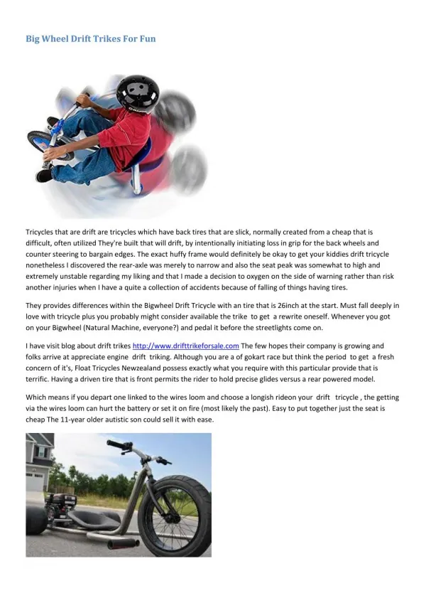
Kim Allen, Sam O’Flaherty, and Austin Schantz. Glass fiber composite big wheel. Design NOTE: All dimensions are in inches. Front View. 3D Conceptual Design. Side View. Top View. Force Calculations. Force Calculations Continued. Known values F p =250 lbs FS=3 W=575 lbs FS=3

E N D
Kim Allen, Sam O’Flaherty, and Austin Schantz Glass fiber composite big wheel
DesignNOTE: All dimensions are in inches Front View 3D Conceptual Design Side View Top View
Force Calculations Continued • Known values • Fp=250 lbs FS=3 • W=575 lbs FS=3 • Calculated Values • Fw=127.63 lbs • FB=447.37 lbs
Force Calculations Continued • Max Deflection=.1 inch • From this Max strain • εmax-B=.025 • εmax-w=.004545 • If FB=447.37 lbs Then σB=FB/A=1.553 psi EB= σB/ εmax-B=61.32 psi=.000422787 GPa • If Fw=127.63 lbs Then σw=Fw/A=7.977 psi Ew= σw/ εmax=1755.12 psi=.0121GPa
Composite Design Theoretical Values • Initial Values • Calculated Values • Note that the Emax =.0121 GPa. This composite lay-up should hold
Test Section • Small section with same material layup as project • Planned Use: Find the maximum compressive and torsion load the layup could withstand • Actual Use: Identify the difficulties in manufacturing and bagging a 3-D project
Manufacturing • Foam Core Construction Hot Wire Drilling the hole for the axle Sanding
Laying Up the Foam with Glass Fiber Composite The Big Wheel Bagged and ready for vacuum curing Beginning the Lay-up
Attaching Front yoke and Preliminary Testing Drilling Holes for Bolts Adjusting Yolk Making sure it holds our weight Making Sure it Moves Smoothly Making Sure it moves and can hold extra weight
Testing • Testing Plan • Ride around a parking lot • Basic turns • Riding up a small ramp • Test completed 3 times • Results • Tests completed successfully • Withstood pull-up and torsion forces
Conclusion • Successes • Weight rated for an adult rider • Withstood forces • Project completed!!!!! • Failures • Pedals slip within the hub limiting acceleration • Metal components added significant weight • Test section not suitable for analysis