Download
1 / 131
1.31k likes | 1.49k Views
The SACK option does not change the meaning of the Acknowledgement Number field. Receiver acknowledges all correctly received pkts buffers pkts, as needed, for eventual in-order delivery to upper layer Sender only resends pkts for which ACK not received sender timer for each unACKed pkt

E N D
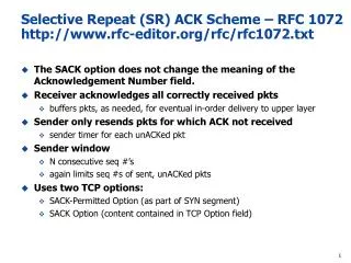
The SACK option does not change the meaning of the Acknowledgement Number field. Receiver acknowledges all correctly received pkts buffers pkts, as needed, for eventual in-order delivery to upper layer Sender only resends pkts for which ACK not received sender timer for each unACKed pkt Sender window N consecutive seq #’s again limits seq #s of sent, unACKed pkts Uses two TCP options: SACK-Permitted Option (as part of SYN segment) SACK Option (content contained in TCP Option field) Selective Repeat (SR) ACK Scheme – RFC 1072 http://www.rfc-editor.org/rfc/rfc1072.txt
The 2-byte TCP Sack-Permitted option may be sent in a SYN by a TCP that has been extended to receive (and presumably process) the SACK option once the connection has opened. It MUST NOT be sent on non-SYN segments. The SACK option is to be used to convey extended acknowledgment information from the receiver to the sender over an established TCP connection. How SACK Option Is Exchanged Between Sender and Receiver Using the TCP Option Field
The SACK option is to be sent by a data receiver to inform the data sender of non-contiguous blocks of data that have been received and queued. The data receiver awaits the receipt of data to fill the gaps in sequence space between received blocks. When missing segments are received, the data receiver acknowledges the data normally by advancing the left window edge in the Acknowledgement Number Field of the TCP header. The SACK option does not change the meaning of the Acknowledgement Number field. Left Edge of Block: This is the first sequence number of this block. Right Edge of Block: This is the sequence number immediately following the last sequence number of this block. How TCP SACK Handles Non-Contiguous TCP Segments at the Receiver
The recovery of a corrupted PDU proceeds in four stages: First, the corrupted PDU is discarded at the remote node's receiver. Second, the remote node requests retransmission of the missing PDU using a control PDU (sometimes called a Selective Reject). The receiver then stores all out-of-sequence PDUs in the receive buffer until the requested PDU has been retransmitted. The sender receives the retransmission request and then transmits the lost PDU(s). The receiver forwards the retransmitted PDU, and all subsequent in-sequence PDUs which are held in the receive buffer. How Selective-Repeat ACK Works
Operation of Selective Repeat: The sender transmits four PDUs (1-4). The first PDU (1) is corrupted and not received. The receiver detects this when it receives PDU(2), which it stores in the receive buffer and requests a selective repeat of PDU(1). The sender responds to the request by sending PDU(1), and then continues sending PDUs (5-7). The receiver stores all subsequent out-of-sequence PDUs (3-4), until it receives PDU(1) correctly. The received PDU (1) and all stored PDUs (2-4) are then forwarded, followed by (5-7) as each of these is received in turn How Is The Destination TCP Buffer Affected by the Selective-Repeat Scheme?
Sliding Window Protocols:Go-back-N and Selective Repeat p: the loss rate of a packet; M: number of seq# (e.g., 3 bit M = 8); W: window size
Many programs will use a separate TCP connection as well as a UDP connection TCP Multiplexing
By specifying ports and including port numbers with TCP/UDP data, multiplexing is achieved Multiplexing allows multiple network connections to take place simultaneously The port numbers, along with the source and destination addresses for the data, determine a socket TCP Multiplexing
Concerns with the performance optimization of operational networks This concern was due to the fact that IGP routing always selects least-cost path from source to destination that can lead to over-utilized and under-utilized links Need a tool that allows us to “steer” traffic so that can lead to more balanced flow of traffic across links based MPLS Concept of Traffic Engineering (TE)
Pros: The layering and encapsulating concept is useful by breaking out larger problems into smaller & manageable layers The layering model is logical and therefore provides opportunity for technology adaptation (sub-layering) Cons: Data encapsulation can reduce throughput and efficiency of each layer because they are not aware of the packetization process that happens in the lower layers Tweaking TCP window size and MTU size is a challenge in real life The TCP and IP packet formats do not lend themselves to strong security SSL and IPSec had to be added later to solve this problem Pros and Cons of the TCP/IP Model
A Motivation For MPLS - The Hyper-Aggregation Problem Traffic for “Washington” SPF routed many under-utilized links 4 over-utilized links Washington San Jose MASSIVE CONGESTION CONGESTION
One of the primary original goals of MPLS, boosting the performance of software-based IP routers, has been superseded as advances in silicon technology have enabled line-rate routing performance implemented in router hardware. In the meantime, additional benefits of MPLS have been realized, notably VPN services (layer 2 or layer 3) and traffic engineering. How Is MPLS Used?
Network Engineering "Put the bandwidth where the traffic is" physical cable deployment virtual connection provisioning Traffic Engineering "Put the traffic where the bandwidth is" on-line or off-line optimisation of routes route diversify Network Engineering and Traffic Engineering
Mechanisms bandwidth over-provisioning metric manipulation Limitations some links become under-utilized or over-utilized trial-and-error approach expensive Layer 3 Routing Network Engineering Adds Bandwidth 1 Washington San Jose 1 2 1 1 IGP Metrics
Traffic Engineering Distributes Traffic TE-distributed traffic over the network resources Washington San Jose
MPLS is not a routing protocol; it works with layer 3 routing protocols (BGP, IS-IS, OSPF) to integrate network layer routing with label switching. Not just QoS: A way to set up connections and treat the connection in a certain way Traffic Engineering – steer it this way QoS is another “way this connection should be treated” Establish a Forwarding Equivalence Class (FEC) at the ingress, and map the IP packets to the FEC An FEC represents a group of packets that share the same requirements for their transport (Delay, Jitter, Packet Loss, etc…) The FEC has a label value – a fixed value, no mask (like IP destinations) Once the label is assigned, packets are forwarded (switched) according to the label and not the destination IP address Faster lookups on fixed-length values than on variable-length values Very similar to ATM and Frame Relay switching Runs over layer 2 vs RSVP which runs over layer 3 More secure MPLS Operating Planes Data Plane = label swapping and forwarding labeled packets Control Plane = routing, signaling and control protocols that assign lables to IP routes/prefixes Existing protocols: Label Distribution Protocol (LDP) or RSVP-TE Think of an LDP as being an official way for one LSR to say to another "let's use this label to get stuff to this destination really fast". MPLS: MultiProtocol Label Switching
MPLS Shim Header Format + Label bits—Twenty bits + EXP bits—Three bits for class of service information; these bits are variously called the experimental bits, class of service (CoS) bits, or type of service (ToS) bits. The EXP bits are mapped from the IP packet at the ingress node and are mapped back into the IP packet at the egress node. + S bit—One bit to indicate whether the label is on the bottom of the label stack. + TTL bits-Eight bits for a time-to-live indicator. The TTL bits are mapped from the IP packet at the ingress node. The TTL bits in the shim header are decremented at each hop.
As packets enter the MPLS network, they are mapped to labels based on their destination IP addresses Routers that run MPLS are known as Label Switching Routers (LSRs) The MLPS connection is called a Label-Switched Path (LSP) All packets going to a single destination with similar characteristics (e.g., QoS) belong to the same Forwarding Equivalence Class (FEC) MPLS Architecture
A Forwarding Equivalence Class (FEC) is a class of packets that should be forwarded in the same manner (i.e. over the same path). A FEC is not a packet, nor is it a label. A FEC is a logical entity created by the router to represent a class (category) of packets. When a packet arrives at the ingress router of an MPLS domain, the router parses the packet's headers, and checks to see if the packet matches a known FEC (class). Once the matching FEC is determined, the path and outgoing label assigned to that FEC are used to forward the packet. FECs are typically created based on the IP destinations known to the router, so for each different destination a router might create a different FEC, or if a router is doing aggregation, it might represent multiple destinations with a single FEC (for example, if those destinations are reachable through the same immediate next hop anyway). The MPLS framework, however, allows for the creation of FECs using advanced criteria like source and destination address pairs, destination address and TOS, etc. Forward Equivalent Class (FEC) – What it means
Introduced in MPLS standards to denote packet forwarding classes Comprises traffic to a particular destination to destination with distinct service requirements Why FEC? To precisely specify which IP packets are mapped to each LSP Done by providing a FEC specification for each LSP Forwarding Equivalence Class (FEC)
Ingress Label FEC Egress Label 6 138.120.6.0/24 9 Forward Equivalent Class (FEC) Classification • A packet can be mapped to a particular FEC based on the following criteria: • destination IP address, • source IP address, • TCP/UDP port, • class of service (CoS) or type of service (ToS), • application used, • … • any combination of the previous criteria.
FEC Concept – Assigning a label with an incoming FEC using IP header info
IP Routing With Routing Table B.0 Z 2 Z Z Z.0 1 3 1 2 A.0 C.0 R2 R1 Dest. Next Hop Cost Port Dest. Next Hop Cost Port A.0 direct 0 1 A.0 R1 1 1 B.0 direct 0 2 B.0 R1 1 1 C.0 direct 0 3 C.0 direct 0 1 Z.0 R2 1 3 Z.0 direct 0 2
Routing with MPLS Label Forwarding Information Base (LFIB) Q: create LFIB for R4 => R3 => R2 => R1
Routing Comparisons - IP and MPLS IP Network Access Link Router Router Washington Router San Jose Customer Site-B Customer Site-A Router MPLS Network LSP E-LER I-LER Washington LSR San Jose Customer Site-B Customer Site-A LSR
LSR =Label Switching Routers - routers or switches that handle MPLS and IP traffic; they swap labels LER = Label Edge Routers - LSRs at the edge of MPLS networks I-LER = Ingress LERs - classify unlabeled IP packets and push labels E-LER = Egress LERs - pop labels and route unlabeled IP packets LSP = Label Switched Paths -path between I-LER and E-LER created by MPLS; LSPs are always uni-directional MPLS Technology Map E-LER Washington I-LER LSR San Jose LSR LSP
Ingress @ I-LER PUSH the label: assign the traffic to an LSP or “get on” the LSP here Transit @ LSRs SWAP the label: switch the packet according to label info Exact-match versus longest-match Egress @ E-LER POP the label at the end of the LSP, strip the label Penultimate Hop Popping “Cheat”: strip the label at the second-to-last router This is done by the E-LSR send a label value of 3 to the penultimate Router Helps offload the processing done by the E-LER Actions at LERs and LSRs
Data Flow in an MPLS Networks - LERs Much like the mail room that classifies mail to your branch location into routine, priority and overnight mail, the Label Edge Router classifies traffic. In MPLS, this classification process is called forward equivalence class, or FEC for short. The LER are the big decision points. LER are responsible for classifying incoming IP traffic and relating the traffic to the appropriate label. This traffic classification process is called the FEC (Forward Equivalence Class). LER use several different modes to label traffic. In the simplest example, the IP packets are “nailed up” to a label and an FEC using preprogrammed tables such as the example shown in table below. The LER are the big decision points. LER are responsible for classifying incoming IP traffic and relating the traffic to the appropriate label. This traffic classification process is called the FEC (Forward Equivalence Class).
MPLS LSRs The function of LSR is to examine incoming packets. Providing that a label is present, the LSR will look up and follow the label instructions, and then forward the packet according to the instructions. In general, the LSR performs a label swapping function
MPLS LSP LSP established between MPLS-aware devices. Because MPLS works as an overlay Protocol to IP, the two protocols can co-exist in the same cloud without interference.
Labels are locally significant; can be switched at each leg of the connection Downstream router assigns label to upstream router Header and label formats: Figure 8-19 Header is 32 bits, including 20 bits of label, 3 bits of CoS Protocols to distribute labels between routers: RSVP and LDP Multiple labels in a Label Stack Label Assignment and Distribution
L3 VPN L3 VPNs. MPLS VPNs fall into two broad classes those that operate at Layer 3 and those that operate at Layer 2. Layer 3 VPNs were first to be investigated and standardized in RFCs. Layer 3 VPNs based on RFC 2547bis have seen the most widespread deployment to date. RFC 2547bis-based Layer 3 VPNs use extensions to BGP, specifically Multi-Protocol internal BGP (MP-iBGP), to distribute VPN routing information across the provider backbone. Standard MPLS mechanisms (as previously discussed) are used to forward the VPN traffic across the backbone. In an L3 VPN, the CE and PE routers are IP routing peers. The CE router provides the PE router with the routing information for the customer's private network behind it. The PE router stores this private routing information in a Virtual Routing and Forwarding (VRF) table; each VRF is essentially a private IP network. The PE router maintains a separate VRF table for each VPN, thereby providing appropriate isolation and security. VPN users have access only to sites or hosts within the same VPN. In addition to the VRF tables, the PE router also stores the normal routing information it needs to send traffic over the public Internet. L3 VPNs use a two-level MPLS label stack (see Figure 3). The inner label carries VPN-specific information from PE to PE. The outer label carries the hop-by-hop MPLS forwarding information. The P routers in the MPLS network only read and swap the outer label as the packet passes through the network. They do not read or act upon the inner VPN label that information is tunneled across the network. The L3 VPN approach has several advantages. The customer IP address space is managed by the carrier, significantly simplifying the customer IT role as new customer VPN sites are easily connected and managed by the provider. L3 VPNs also have the advantage of supporting auto-discovery by leveraging the dynamic routing capabilities of BGP to distribute VPN routes. The Layer 3 approach has disadvantages as well. Layer 3 VPNs support only IP or IP-encapsulated customer traffic. Scaling also can be a significant issue with PE routers required to support BGP routing tables that are larger than normal with the addition of the VPN routes.
LSR 1 LSR 2 LSR 3 LSR 4 Example of How Labels Are Mapped 1. Label Request Label Request <LSR2, LSR3, LSR4> Label Request <LSR3, LSR4> Label Request <LSR4> A B Label Mapping <32> Label Mapping <24> Label Mapping <17> 2. Label Mapping
LSPs for Different Traffic Types Image taken from Voice over IP Solutions, Juniper Networks, June 2001
Advanced Topic IP Sec
Integrity : Received = Sent Availability: Legal users should be able to use system. Ping Confidentiality: No wiretapping and snooping Authentication: You are who you say you are Authorization: Access Control Network Security 101
A single key is used to both encrypt and decrypt a message. A secure channel must be in place for users to exchange this common key. Secret Key Secret Key Encrypted Message Cryptographic Methods - Secret Key (symmetric) Cryptography Plaintext Message
Alternate Way to Provide Symmetric Cryptography - Hash Functions In cryptography, a cryptographic hash function is a hash function with certain additional security properties to make it suitable for use as a primitive in various information security applications, such as authentication and message integrity. A hash function takes a long string (or message) of any length as input and produces a fixed length string as output, sometimes termed a message digest or a digital fingerprint. A hash function at work
Two keys are used for this method, the public key is used to encrypt. The private key is used to decrypt. This is used when it isn’t feasible to securely exchange keys. Jay’s Public Key Encrypted Message Frank Jay’s Private Key Clear Text Cryptographic Methods- Public Key (asymmetric) Cryptography