Download
1 / 24
260 likes | 568 Views
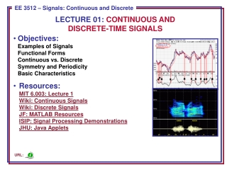
From Continuous Time System to Discrete Time System . ES400 Jack Ou, Ph.D. Chapter 1. Outline. Modeling Signal System Continuous Time System ADC Discrete Time System. Signals. Signals are divided into two natural categories

E N D
From Continuous Time System to Discrete Time System ES400 Jack Ou, Ph.D. Chapter 1
Outline • Modeling • Signal • System • Continuous Time System • ADC • Discrete Time System
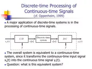
Signals • Signals are divided into two natural categories • Continuous time signal: Discrete time signal: defined at only defined for all values of time • Discrete Time Signal: Only defined at certain instants of time.
Example of a Continuous Time Signal • Criterion: The signal defined for all values of time • Techniques: Fourier series, Fourier transform, Laplace transform
Example of a Discrete Time Signal • Criterion: The signal is defined for at only certain instants of time • Technique: Z transform, DFT, FFT
Mathematical Solutions of Physical Problems Formulate a math model for physical signal and system involved. Equations are solved for typical excitation function. Compare math solution with the response of the physical system Iterate the process until close correlation between the measured and model is achieved.
Use KVL to formulate the mathematical representation of a physical system • KVL: The algebraic sum of Voltages around any closed loop in an electric circuit is zero.
Solve the problem in the Laplace Domain • Laplace transform the KVL expression • Solve the variable of interest • Inverse Laplace Transform
Not All Systems Can Be Represented Using a Continuous Time Representation
Convert a Signal From Continuous Time System to Discrete Time System • Operational Amplifier • Digital to Analog Converter • Comparator • Counter-Ramp Analog to Digital Converter
Operational Amplifier If used in a feedback configuration, V+=V-. Large input impedance!
Digital-to-analog Converter Purpose: Convert a binary number to a voltage.
A Simple Digital to Analog Converter Assume “1”=5V, “0”=0V D0=“1”, D1=“0”, D2=“0” What is Vout?
Comparator If Vi>Vr, then Vo=“1” Else zero.
A Analog-to-digital Converter (Inverter) (NAND) EOC: End of Conversion A binary output approximately equal to Vx will be when EOC=1