Solid Modeling
Solid Modeling . Engineering Graphics Stephen W. Crown Ph.D. Objective. To learn how to generate solid models in CAD To understand how to use solid modeling in the design process. Overview. Primitives Extrude Sweep Revolve Blend Solid Model Operators Viewing Solid Models.

Solid Modeling
E N D
Presentation Transcript
Solid Modeling Engineering Graphics Stephen W. Crown Ph.D.
Objective • To learn how to generate solid models in CAD • To understand how to use solid modeling in the design process
Overview • Primitives • Extrude • Sweep • Revolve • Blend • Solid Model Operators • Viewing Solid Models
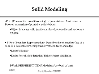
Solid Models • Definition: A 3-D model of an object that contains volumetric information • Mass can be represented • Interior surfaces are generated automatically as portions of an object are removed • Easily constructed using primitive shapes, extruding, and revolving
Solid Primitives • Box (Parallelepiped) • Cylinder • Cone • Sphere • Wedge
Example: Using Primitives • Box • Wedge • Union / Protrusion • 6 boxes • 2 wedges • Subtract / Cut • 1 box - minus 2 wedges • 1 box - minus 2 boxes
EXTRUDE • Two dimensional closed objects can be extruded to give solid objects • The direction of the extrusion is typically normal to the 2-D cross sectional sketch • The height of extrusion can be specified
SWEEP • The path of the extrusion must be defined (trajectory) • The extruded cross section must be defined • The cross section stays normal to the path
REVOLVE • Two dimensional closed objects can be revolved to give solid objects • The axis of rotation must be defined • The angle of revolution must be specified
BLEND • Smooth transition can be made between two closed shapes with similar geometry (i.e. equal number of vertices) • The distance between sections must be defined • The angle of twist between sections must be specified
Solid Model Operators • Subtract / Cut • Intersection • Union / Protrusion
Solid Model Operators • Subtract / Cut • subtracts one solid from another • One solid is subtracted from the other.
Solid Model Operators • Intersection • Creates a solid that represents the region that is in common to the selected solids
Solid Model Operators • Union / Protrusion • Creates a single solid from two solids that intersect
Example: Solid Model Operators What procedure would you follow to create the two mating parts? • Create the bounding box for the upper part • Create the two cylinders • Subtract the cylinders from the box • Create the bounding box for the lower part • Subtract the finished upper part
Example: Solids from Drawings • Extrude the view with the most detailed perimeter • The depth of the extrusion may be found from an adjacent view
Example: Solids from Drawings • Use the perimeter of other views to make additional cuts • Interpret interior details by making assumptions about geometry in one view and testing them in adjacent views
Example: Solids from Drawings • Verify that the completed part satisfies every view • Generate a multiview drawing from the solid part and compare to the original sketch or drawing
Using Solid Modeling for Design • Intersection of wedge and cylinders is not clearly defined • Construction of solid model forces resolution regarding details of construction
Using Solid Modeling for Design • Intersection of wedge with post produces a gap, a ledge, or a circular groove • Intersection of wedge with base produces a ledge, an overhang, or requires a rounded end • These details can be shown in the multiview drawing but are more obvious in the solid model
Viewing Solid Models • Rendering Styles • Wireframe with hidden lines • Hidden lines removed • Shaded
Viewing Solid Models • LIGHTING • Distance, Point, Spotlight • Ambient light • Intensity • Modify (specify location of light) • SURFACE FINISH • Specify roughness, color, sensitivity to ambient light, texture maps, and bump maps • Apply finishes to individual parts or assemblies