Download

1 / 47
470 likes | 696 Views
Experience in Formal Model Verification for Mission-Critical Domains. By Vladimir Okulevich Quantitative Aspects of Embedded Systems Schloss Dagstuhl, Germany 0 5 .03.2007- 09 .03.2007. Content. Introduction Software Dependability Formal Model Verification Examples: A,B,C

E N D
Experience in Formal Model Verification for Mission-Critical Domains By Vladimir Okulevich Quantitative Aspects of Embedded Systems Schloss Dagstuhl, Germany 05.03.2007-09.03.2007
Content • Introduction • Software Dependability • Formal Model Verification • Examples: A,B,C • Summary, Challenges
Corporate Technology Core technologies, competencies and services for the Groups Customer Business Areas / Operating Groups top+ company programs • Innovation • Customer focus • Global competitive-ness Regions AutomationandControl Information andCommunications Power Transportation Lighting Health Care Corporate Research and Technologies • Core technologies and competencies with multiple impact supporting the groups • Pictures of the Future • Accelerators for new business opportunities Corporate Intellectual Property and Functions • Intellectual Property services and strategy • Standardization, environmental affairs, Information research center Corporate Technology
Time horizons of the R&D activities of the business groups and Corporate Technology R&DExpenses BusinessGroups Total R&D expenses CorporateTechnology Time to market Today One product generation in the future Two product generations in the future (Absolute time scale depends on business) A seamless transition from R&D in Corporate Technologyto the Business Groups is crucial for our success
St. Petersburg München Perlach Dependability Competence Team at Siemens CT SE OOO CT SE Dependability Development Infrastructure Requirement Engineering Model Driven Development Software Testing Code Quality Management Dependability Engineering Verification & Certification Software Architectures Real-time Technology Embedded Platforms Fault-Tolerance … OOO CT SE Linux Berlin Princeton, NJ Beijing Roke Manor, Romsey Berkeley, CA Moscow Tokyo Erlangen CT SE 1Development Techniques CT SE 2Architecture Bangalore
Dependability in Siemens products Integrity Safety Maintainability Dependabilityin Siemens Products Availability Reliability Confidentiality Almost all Siemens Business Units develop and sell products that perform mission-critical operations. Most of these products nowadays contain an ever increasing software part.
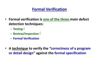
Definitions: Dependability Attributes • Dependability is an integrative concept that encompasses the following system attributes: • Availability: readiness for correct service • Reliability: continuity of correct service • Safety: absence of catastrophic consequences on the user(s) and the environment • Confidentiality: absence of unauthorized disclosure of information • Integrity: absence of improper system state alterations • Maintainability: ability to undergo repairs and modifications • Compound attributes: • Survivability: system capability to resist a hostile environment so that it can fulfill its mission (MIL-STD-721, DOD-D-5000.3) • Security: Dependability with respect to the prevention of unauthorized access and/or handling of information (Laprie, 1992) * RAM / RAMS: acronyms for reliability, availability, maintainability, and safety
Fundamental Concepts of Dependability(A. Avizieniz, J.-C. Laprie, B. Randell) Concepts of Dependability developed by A. Avizieniz, J.-C. Laprie, B. Randell
Focus of CT Software Engineering Dependability Engineering Group Focus of Dependability Engineering Group Concepts of Dependability developed by A. Avizieniz, J.-C. Laprie, B. Randell
Dependability Relevant Standards and Guidelines DependabilityManagement Functional Safety IEC 61508 ISO 9000-4 TestingNFRs ISO 9126 Miscellaneous:aviation e.g. Automotive Rail IEC 61713 CENELEC EN 5012x MISRA guidelines RTCA DO-178B MISRA C standard BS 7925-1 FAKRA/ISO (draft) BS 7925-2
Outline of Formal Model Verification • Main Steps: • Objects under Analysis • identification in software project • Correctness properties definition • for Objects under Analysis • Creation of model for • Objects in PROMELA • Model verification by SPIN and • findings analysis • Report preparation on • verification results • Further promising actions: • Automate procedure of model creation from C/C++ sources
formalizeextract derive FormalProperties Formal Model Checker Formal Model deriveadd.tests Verification Results cont. refine Embedding Formal Verification into Software Development Life-Cycle Informal Design / Code Requirements Product Software under Test certified certified • Test Sequences • rcv[pv][0][0][nok] • resume • send[1][0][1][0] • rcv[pv][0][1][ok] • resume • send[1][0][1][1] • ... Beware of bugs in the above code; I have only proved it correct, not tried it. [Donald E. Knuth, 1977]
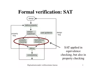
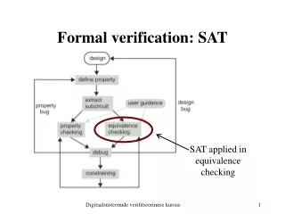
Output (verification result) Model Specification Exhaustive Verification Syntax Checker Probabilistic Verification Correctness Requirement Failtrace (if exists) LTL, Omega- regular automata Sequence of total model state and subsequent changes in model Settings Formal Model Verification – SPIN tool • Model in PROMELA (C-like language) is automatically translated into the extended FSMs. • These FSMs are verified to be correct according to correctness requirements. • Correctness requirements are presented in Linear Temporal Logic (LTL) • SPIN (Bell Labs, G. Holzmann): • Characteristics of method: • 1) exhaustive verification • 2) space compression • 3) probabilistic verification (hashing) • SPIN-based technologies are used: • Bell-Labs (network switches, OS Plan 9) • NASA (Cassini mission at Saturn, Deep Space 1) • Siemens CT
HintsBefore Start of Model Checking (1) Why to do? • Solve Problems • Review/Assessment Objects? • Protocol • Components set Properties? • “Executablility” • Safety • Integrity • Normal/Failure Modes
HintsBefore Start of Model Checking (1+) Why to do? class a { char name[MAXLEN]; ... }; a::~a { if (name!=NULL) free(name); }; // it had been working in field about half of a year. • Solve Problems • Review/Assessment Objects? • Protocol • Components set Properties? • “Executablility” • Safety • Integrity • Normal/Failure Modes
HintsBefore Start of Model Checking (2) Why to do? How to check? • Solve Problems • Review/Assessment • Efforts • Tools/Licenses Objects? • Protocol • Components set Input Materials? Properties? • Requirements • Design Specifications • Source Code • Test Cases • “Executablility” • Safety • Integrity • Normal/Failure Modes
HintsBefore Start of Model Checking (3) Why to do? How to check? What to do after? • Solve Problems • Review/Assessment • Efforts • Tools/Licenses Objects? • Prove Adequacy • Validate Results • Apply Results • Generate Tests • Update Design • Protocol • Components set Input Materials? Properties? • Requirements • Design Specifications • Source Code • Test Cases • “Executablility” • Safety • Integrity • Normal/Failure Modes
Analysis Level and Input Materials for Formal Model Verification • Selected Analysis Level and Type of Input Materials: important factors for analysis goals, realization and application. Requirements Design Specifications Formal Model Verification Source Code Test Descriptions
Example A Analysis Level and Input Materials • Example A - Source Code analysis of Line Discipline Driver forUnix-compatible operation system. Scope: software component. Requirements Design Specifications Formal Model Verification Source Code Test Descriptions
Example A System Structure • Customized Line Discipline • Serial Line:57600 bps • Error Protection: • Serial Line: Parity Bit • Protocol Level: BCC for data in messages • System Object under Analysis • Peer Device
Example A Model of Software Driver • States: depend on message stream. • DRV Messages: • STX • ETX • DLE • …
TFirstChar TLength TData ? ? DLE DLE TLastChar TDLE2 Example ASafety Property (1) • Safety Property: Any order of STX_DATA and DLE messages will be correctly received and Receiver achieves TFirstChar state after TDLE2 state. • Modeling Solution: Sender generates valid messages STX_DATA and DLEin all possible sequences. • Property Parts: • #define a (ReceiveState==TDLE2) • #define b (ReceiveState==TFirstChar) • Safety Property for Model Verification • in Linear Temporal Logic: • [] (<> a -> <> b) STX_DATA STX_DATA STX_DATA OK:Property Valid
Example A Safety Property (2) • Safety Property: Any order of STX_DATA and DLE messages will be correctly received and Receiver achieves TFirstChar state after TDLE2 state if the noise char comes suddenly. • Modeling Solution: Sender generates valid messages STX_DATA and DLEin all possible sequences. We allow receiving of noisy char. • Property Parts: • #define a (ReceiveState==TDLE2) • #define b (ReceiveState==TFirstChar) • Safety Property for Model Verification • in Linear Temporal Logic: • [] (<> a -> <> b) x DLE ? DLE STX_DATA STX_DATA STX_DATA Error: Property Invalid TFirstChar TLength TData TLastChar TDLE2
Example A Error Analysis for Property (2) : Source Code Error: Property Invalid Explanation:SPIN shows that DRV could be blocked if noisy (incorrect) char came after TDRVDLE. NOTE: the real driver will wait 50 timeouts (~5-20 sec) before it starts receiving of next telegram (e.g. STX_DATA) • switch (theDriverData->ReceiveState) { • case TFirstChar: • switch (theChar) { • (…) • case TDRVDLE: • theDriverData->ReceiveState = TDLE2; break; • } • (…) • case TDLE2: • if(theChar == '?' || theChar == TDRVENQ) • theEvent = TDLEReceived; • if(atomic_read(&theDriverData->WabtCounter) == 50) { • atomic_set(&theDriverData->WabtCounter, 0); • theDriverData->ReceiveState = TFirstChar; • } • break; • (…) TFirstChar TLength TData TLastChar TDLE2
STX LEN ‘A’ ‘B’ BCC Example A Safety Property (3) • Safety Property: After start of the Data Receiving the DRV Line Discipline always receives first byte of the Source Message if the BCC is correct. • Modeling Solution: Sender generates simple message which includes 2 bytes “A”,”B”(let’s to see it as “alarm message”). The Telegram is the following: • Modeled: • (1) • Property Parts: • #define a (ReceiveState==EData) /* We started data receiving */ • #define b1 (RecvBuffer[1]=='A') /* 1st byte OK */ • Safety Property for Model Verification in Linear Temporal Logic: • [] (<> a -> <> (b1)) OK:Property Valid
STX LEN ‘A’ ‘B’ BCC Example A Safety Property (4) • Safety Property: After start of the Data Receiving the DRV Line Discipline always receives all bytes of the Source Message if the BCC is correct. • Modeling Solution: Sender generates simple message which includes 2 bytes “A”,”B”(let’s to see it as “alarm message”). The Telegram is the following: • Modeled: • (1) LEN=DATA_LEN+1=3 • Property Parts: • #define a (ReceiveState==EData) /* We started data receiving */ • #define b1 (RecvBuffer[1]=='A') /* 1st byte OK */ • #define b2 (RecvBuffer[2]=='B') /* 2nd byte OK */ • Safety Property for Model Verification in Linear Temporal Logic: • [] (<> a -> <> (b1 && b2)) Error: Property Invalid
Example A Error Analysis for Property (4) : Source Code Error: Property Invalid Explanation:SPIN found that last byte of data in any message (including “alarm” message) is lost. • switch (ReceiveState) { • (…) • case TLength: • theDriverData->TelegramLength = theChar; • theDriverData->ReceiveBCC = theChar; • theDriverData->ReceiveLength = 1; • theDriverData->RecvBuffer[0] = ST_DATA; • theDriverData->ReceiveState = TData; • break; • case TData: • theDriverData->ReceiveBCC ^= theChar; • --theDriverData->TelegramLength; • if(theDriverData->TelegramLength <= 1) { • theDriverData->ReceiveState = TTastChar; • } else { • theDriverData->RecvBuffer[theDriverData->ReceiveLength] = theChar; • ++theDriverData->ReceiveLength; • } • break; • case TLastChar: • if(theDriverData->ReceiveBCC == theChar) { • theEvent = TDataReceived; • } else { • DPRINTK(10, “DRV: Wrong BCC!!!\n"); • } • theDriverData->ReceiveState = TFirstChar; • break; • case TDLE2: (…) };
Example A FMV Results for the Driver • Results from SPIN: • Long delay identified if 1 noise char comes • Data lost in telegram receiving found • Model-building review: • Performance bottleneck could create high interrupts latency • Wrong API-version calls • “Magic Constants” used in code • “Dead Code” identified
Example B Analysis Level and Input Materials • Example B – Design Specifications analysis of Distributed Safety-related Control System. Scope: a few user-level functions. Requirements Formal Model Verification Design Specifications Source Code Test Descriptions
PROC_RUN==1 && SIGNAL_A==0 && SIGNAL_B==0 Example B Deadlock Possibility Identified by SPIN 1 P1 0 0 1 P2 1 1 Deadlock possibility due to delay in M1
Example B Livelock Correction Livelock Correction
Results from SPIN: Livelock identified Deadlock identified Possible Deadlock found Design Specifications updated according hypotheses Model-building Review: Design Specification omissions and errors identified (> 60) Recommendations for improvement proposed Example BResults
Example C Analysis Level and Input Materials • Example C – Requirements, Design Specifications and Source Code analysis of Hot-Reserved Processing Units.Scope: Activity Arbitrage Angorithm. Requirements Formal Model Verification Design Specifications Source Code Test Descriptions
Example C - Hot-Reserved Processing Units System Description • System Description: Two Hot-reserved Processing Units (PU) are Managing Devices through theirDevice Buses. PU should be synchronized together to Manage Devices. • Interfaces types between PU: • 3 discrete lines • messages in UDP datagrams (over Ethernet).
Example C - Hot-Reserved Processing Units Idea of Algorithm and Verification Requirement • Safety requirement: Only 1 Active PU or no one PU should be Active at the moment to Manage Devices. • Events in model: • #define a (flagActive[PU_A]==1) • #define b (flagActive[PU_B]==1) • Formula in Linear Temporal Logic: • [] ((!a && b) || (a && !b) || (!a && !b)). • where [] – LTL operator “ALWAYS” • Activity Arbitrage Algorithm (A3) – to select Master/Slave PU. • Idea for A3: algorithm of PU communication for arbitrage activity should use both interfaces and sets up active PU for Device Management. • Task: Develop communication algorithm based on the Idea for A3 and conformed to Safety requirement.
Example C - Hot-Reserved Processing Units Structure of the Model
Example C - Hot-Reserved Processing Units Part of Model • proctype PULevel1(byte ID;chan qTX,qRX) • { byte p,c,u; /*local copies*/ • do • :: atomic { p=P[ID]; c=C[ID]; u=U[ID]; } • if :: stateLevel1[ID]==s_fail -> • if :: atomic { (((c==false) || (c==true)) && /*CAN_L*/ • ((u==Z) || (u==false))) -> stateLevel1[ID]=s_local; } • :: atomic { (((p==Z) || (p==false)) && (c==Z) && /*CAN_R*/ • ((u==false) || (u==true))) || • ((p==true) && (c==Z) && (u==true)) || • (((c==false) || (c==true)) && (u==true)) -> stateLevel1[ID]=s_pair; } • :: else -> skip; fi; • :: stateLevel1[ID]==s_local -> • if :: atomic { (((c==Z) && (u==Z)) || /*CAN_F*/ • ((p==true) && (c==Z) && (u==false))) -> stateLevel1[ID]=s_fail; } • :: atomic { (((p==Z) || (p==false)) && (c==Z) && /*CAN_R*/ • ((u==false) || (u==true))) || • ((p==true) && (c==Z) && (u==true)) || • (((c==false) || (c==true)) && (u==true)) -> stateLevel1[ID]=s_pair; } • :: else -> /*local mode activity selection*/ • if :: atomic { (c==false) && ((u==Z) || (u==false)) -> flagActive[ID]=false; /*passive*/ } • :: atomic { (c==true) && ((u==Z) || (u==true)) -> flagActive[ID]=true; /*active*/ } • :: else -> skip; fi; fi; … fi; od; }
Example C - Hot-Reserved Processing UnitsFMV Results for Activity Arbitrage Algorithm • Results: • Requirements for the Algorithm were specified in selected format • Independent Review of Requirements was done • >10 errors were found in basic algorithm • Final version of model and Correctness properties were defined • Result model was verified and used for system implementation in C language • Main Test-Cases were defined for system testing • Specifications were updated • Duration: 2 months
Faults Types : Deadlock/Livelock Endangered Safety Integrity violation Correctness violation Non-expected communication order Race Conditions (with different scope) … Additional Focus set on: System Initialization Restart of Components Communication Delays and Faults Objects under Analysis: Protocols and Interfaces (especially under construction) Interacting components (e.g. new architecture or critical mechanism) Data access and control logic in parallel and distributed system Used Principles: Model Slicing “Model Leveling” “Agglutinated Levels” “Aggressive Environment” Summary Objects and Principles
Summary Statements • Summary: • Formal Model Verification is a mean to improve Software Quality • It is a part of Software Development Process • General and Domain standards request application of Formal Methods • Formal Model Verification applicable on different levels: • architecture • critically important mechanisms • Formal Model Verification allows identify errors which: • are difficult “to be caught” by traditional testing • appear as a fault rarely and non-deterministically • Objects for Analysis and Correctness Properties have to be selectedin respect to the project goals
Challenges for Formal Model Verification Challenges • Decrease efforts and qualification needed • Traceability from modeling phase to testing phase • Integration with tools for software development • Automated properties and models extraction from heterogeneous input material … Model Checking is lively important: “the behavior of even nonbuggy distributed applications can easily defy our human reasoning skills.” • Logic Verification of ANSI C code with SPINGerard J. Holzmann
THANK YOU! QUESTIONS?