
Boundary Extraction
E N D
Presentation Transcript
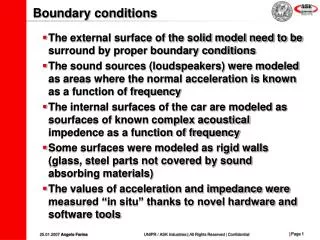
Boundary Extraction The goal of boundary extraction is to find the pixels that are on the boundary of objects in the image. • Course Name: Digital Image Processing Level(UG/PG): UG • Author(s) : Phani Swathi Chitta • Mentor: Prof. Saravanan Vijayakumaran *The contents in this ppt are licensed under Creative Commons Attribution-NonCommercial-ShareAlike 2.5 India license
Learning Objectives After interacting with this Learning Object, the learner will be able to: • Explain the basic morphological Algorithm (Boundary Extraction)
Definitions of the components/Keywords: • The boundary of a set A, denoted as β(A), can be obtained by first • eroding A by B and then performing the set difference between A and • its erosion as follows: • where B is a suitable structuring element. • To extract boundary of a set A: • - First erode A (make A smaller) using structuring element B • - A – erode(A) • The thicker boundaries can be obtained by increasing the size of structuring element. 1 2 3 4 5
Master Layout 1 1 Image after boundary extraction Original Image 2 3 • Give radio buttons to select any one structuring element of sizes 5x5, 7x7, 11x11 • The structuring elements (SE) are 4 5
Step 1: 1 2 3 4 5
Step 2: SE 5x5 1 2 3 4 5
Step 3: 1 2 3 4 5
Step 4: 1 2 3 4 5
Step 5: 1 2 3 4 5
Step 6: 1 2 3 4 5
Step 7: SE 7x7 1 2 3 4 5
Step 8: 1 2 3 4 5
Step 9: 1 2 3 4 5
Step 10: 1 2 3 4 5
Step 11: 1 2 3 4 5
Step 12: SE 11x11 1 2 3 4 5
Step 13: 1 2 3 4 5
Step 14: 1 2 3 4 5
Step 15: 1 2 3 4 5
Step 16: 1 2 3 4 5
Electrical Engineering Slide 1 Slide 3 Slide 23, 24,25 Slide 26 Introduction Definitions Analogy Test your understanding (questionnaire) Lets Sum up (summary) Want to know more… (Further Reading) Interactivity: Try it yourself • Select any one of the figures • a b • c d • Select the size of structuring element 21 Credits
Questionnaire 1 1.If the size of Structuring Element increases, what happens to the width of the boundary? Answers: a) Increase b) Decrease 2 3 4 5
Questionnaire 1 2. Image A Image B:Structuring Element(7x7) What is the boundary extracted image of ‘A’ using structuring element (image B)? Answers: a) b) 2 3 4 5
Questionnaire 1 2. Image a Image b:Structuring Element(7x7) What is the resulting image after eroding the image a using structuring element (image b)? Answers: c)d) 2 3 4 5
Links for further reading Reference websites: http://www.ee.lamar.edu/gleb/dip/10-2%20-%20Morphological%20Image%20Processing.pdf http://faraday.ee.emu.edu.tr/ee583/Lectures/EE%20583-Lecture10.pdf Books: Digital Image Processing – Rafael C. Gonzalez, Richard E. Woods, Third edition, Prentice Hall