Download
1 / 17
170 likes | 197 Views
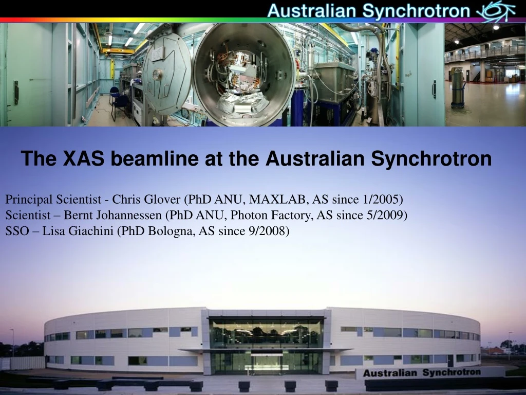
The XAS beamline at the Australian Synchrotron. Principal Scientist - Chris Glover (PhD ANU, MAXLAB, AS since 1/2005) Scientist – Bernt Johannessen (PhD ANU, Photon Factory, AS since 5/2009) SSO – Lisa Giachini (PhD Bologna, AS since 9/2008). Specification / Status.

E N D
The XAS beamline at the Australian Synchrotron Principal Scientist - Chris Glover (PhD ANU, MAXLAB, AS since 1/2005) Scientist – Bernt Johannessen (PhD ANU, Photon Factory, AS since 5/2009) SSO – Lisa Giachini (PhD Bologna, AS since 9/2008)
Specification / Status • Source: 1.9T 40 pole wiggler • Si(111) and Si(311) crystals. Close to theoretical resolutions via use of collimating mirror. • Beamline operated in modes as per table. Limited ability to change modes in a single beamtime. • Transmission and Fluorescence EXAFS capability • 100 Element detector commissioning (ROI mode) • Flux: > 5e12 photon/s for Si(111) in 0.1x0.5 mm FWHM • Focus variable 0.1x0.5 mm to 1 x 2 mm • Harmonic rejection managed by mirrors < 1e-5 • Accepting general users via peer review proposal. Next call for proposals 10 Sept. • xas@synchrotron.org.au • www.synchrotron.org.au
Main Beamline Components Collimating Mirror 1.4m Si substrate 3 Cu fins in l-Ga slots Si, Rh & Pt Stripes SESO 4 bender Accept 2.1 mrad (h) 2.1 – 3.15 mradincid. 1kW max designed heat load Accelcryocooled DCM 25mm fixed offset or pseudo channel cut Si(111) and Si(311) pairs 5 – 40 deg Bragg => 3 – 43 keV 1st and 2nd crystals indirectly LN2 cooled Max designed power load = 700W Accel (Messer) cryocooler RON 905 encoder on Bragg 160 x 80 x 80 mm first crystals rotating around downstream end. 0.5 mm In foil / Cu cooling sandwich. Focussing Mirror 1.4m SiO2 substrate 2 cylinder toroid for different focus / angle of incidence Rh & Pt Stripes SESO U bender 100 x 500 um FWHM
Energy Resolution and Heat Load Theoretical resolutions achieved from M1 bender via backscattering measurements Power load stability superb - not an issue.
Effect of Heatload – repeated scans of Ag edge energy scale is slightly different due to hutch slits (I think?) Spec is 0.3 eV at Rh edge over 24 hrs – basically met.
Power loading tests - V Good Conditions: LN2 4.5 L/min flow at 2.0 Bar = cryocooler 50 Hz. First crystal warms up to 120 K max. Its clear current cooling performance is > 30% better than needed !!!
Energy Stability Performance Monochromator accuracy measured via metal foils to encoder (running in open loop). Repeatability better than 0.1 eV on Si(111) - maximum deviation from tabulated values 0.25 eV! Stability and operation of Messer cryocooler superb - not an issue. No effect of cryocooler seen on beam.
Cryocooler stability Messer cryocoolerstability superb – 0.1% pressure stability – no influence of subcooler fill Fully remote controllable – can cool down DCM from home!
Flux Stability Performance DCM Vibration performance. Compare IC flux fully tuned vs 50% detuned. Tuned – 0.1 % sampled at 100 Hz stability. Detuned on the derivate edge of rocking curve – any motion translate into flux modulations
DCM Vibrations FFT of beam positions – most motion in the vertical = between parallelism of 2 crystals. Lots of work done on DCM already to reduce susceptibility to vibrations: internal clamping of LN2 lines, placing whole DCM on elastomeric damping pads (filtering 25 Hz) – effect has already been reduced by ~ 10x. Clearly, source of vibration in beam related to first and second crystal motions. Coupling of ground (the excitation source) to crystals was via internal LN2 cooling lines. Operate crycooler > 50 Hz so as to not excite resonances. Main remaining problems: 2nd crystal resonance at ~ 44 Hz isolate from 40-45 Hz band in floor
Focussing and Stability Any vibrations translate into flux modulations – and also position. At 12 keV on Si(111) 100 um vertical beam (FWHM) has 15 um vibration (FWHM). Use guard slit at experiment. For Si(311) rocking curve much narrower – effect may be a concern for low noise fluorescence measurements at high energy.
Homogenous sample: Cu foil Cu foil in transmission, 10 repeat scans out to k = 24 A-1.
Problems with saturation of Ion Chambers Oxford Danfysikion chambers found to saturate at relatively low fluxes – now use OKEN ICs – much better linearity Worse if gas is sealed. Currently flowing gas. (Cleaned, baked, re-sealed, difference HP gases tried). For transmission experiments run with 0.5 x 1mm WBSL or with wiggler gap open to 50 mm to reduce flux and use typical gases (eg N, Ar etc). “Bend magnet mode” For high fluxes need to flow He (~ 1/2 bottle a day critical flow). Surprisingly no degradation in performance vs sealed Slow – of the order of 100’s Hz.
226 221 c 213 c 220 c 253 c 220 224 229 226 237 240 c 235 238 219 c 230 235 238 225 235 224 232 237 235 235 234 229 234 231 226 232 229 242 234 233 218 234 231 230 216 213 224 227 230 227 224 218 240 227 223 223 224 213 240 235 231 253 240 230 224 227 232 234 235 240 228 247 227 218 227 219 238 227 230 235 225 238 227 225 210 219 223 225 210 232 217 217 243 227 205 219 222 213 210 228 212 217 223 217 100 Element Ge detector 100 element Ge PAD with XIA DXP electronics arrived July 09. Final cost $1.8 M (AUD). Will be controlled by EPICS (Mark Rivers). Goal is to use XIA electronics in ‘mapping mode’ for on the fly energy scans. Resolution at 5.9 keV, 0.5 uSec shaping time, 100 kcps.
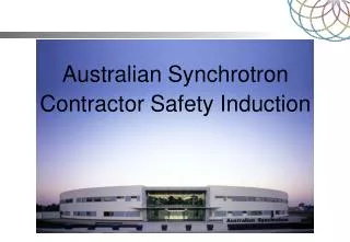
Facilities First experimental hutch is a ‘standard XAFS’ setup Second exp hutch is for non standard / long setup / user supplied equipment 100 Element Ge PAD with XIA DXP electronics delivered July 09. 10 Element Ge + 1 element Si drift detector Harmonic rejection mirror for < 7 keV Closed cycle He cryostat (15 – 300K) Software controllable Keithley gains / sample temperature / motions OKEN ion chambers with flowing gas linear at high fluxes Easy to use scan GUI on top of EPICS subsystems.
Future upgrade Plans • Complete fitout of second hutch: • High temperature furnace • High pressure cell • Q-EXAFS monochromator • IXS setup (RAMAN + RIXS) • Bent Laue analyzer setup • Radioactive sample ‘tent’ • Medium energy XAS beamline on BM • Si – transition metal K edges • Any other suggestions? • Submission deadline 10 Oct 2009.