Download
1 / 25
270 likes | 460 Views
A Large Scale UPS for the Australian Synchrotron. Don McGilvery Lead Accelerator Operator. OUTLINE OF THIS PRESENTATION. About the Australian Synchrotron Light Source Reliability and Causes of Lost Beam Time Types and causes of Power Interruptions

E N D
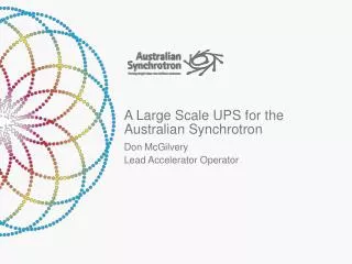
A Large Scale UPS for the Australian Synchrotron Don McGilvery Lead Accelerator Operator
OUTLINE OF THIS PRESENTATION About the Australian Synchrotron Light Source Reliability and Causes of Lost Beam Time Types and causes of Power Interruptions Possible ways to mitigate power interruptions Use of Power Quality data to understand how systems fail Comparison of UPS technological solutions Ups and Downs of a UPS Installation Progress
AUSTRALIAN SYNCHROTRON LIGHT SOURCE • 3GeV electron Light Source • 200mA stored beam (fill on fill) • 216m circ Storage ring • Full energy Injector • Currently 9 beamlines • Operation commenced in 2007 • Supports ca. 2500 Users from Australia and New Zealand • Scheduled 5000 hours of User Beam per year • $35M support facility upgrade program in progress • Seeking Funding for a further 10 beamlines
MAJOR SUPPORT FACILITY UPGRADE Medical and Imaging far field facilities National Centre for Synchrotron Science User Accomodation Building Office expansion Technical Support Facility (Workshops and Engineering Building) Switch Room Extensions 1 3 4 6 2 5
LOST USER BEAM TIME BY FAULT CATEGORIES This equates to a cost of about $560,000.00 in lost productivity due to unreliability of the incoming power feed
AUSTRALIAN SYNCHROTRON POWER FEED The Australian Synchrotron receives its power via a dedicated underground 22KV power feed from a local substation. This in turn receives its power via 66KV feeders from a major substation on the Eastern Australian Power Grid. This grid serves 80% of Australia’s Population across an area of about 2M square kilometers. While the grid is very resilient it is possible for large disturbances to reflect across significant areas of the grid. Often a single event will cause two voltage sag events. When a fault occurs on the Power Grid an automatic circuit breaker will open removing the fault. The voltage returns to normal. Several seconds later the circuit breaker will close again to see if the fault has gone away. If the fault is still present a second dip is seen before the breaker permanently opens.
DISTRIBUTION OF VOLTAGE SAGS% DROP vs DURATION Events between the lines are defined as acceptable by the Power Regulator
COMMON FAULTS CAUSED BY VOLTAGE SAGS • Faults cased by disturbances • @ 95% Storage Ring RF systems trip (SRRF) [TR4] • @ 90% Storage Ring Dipole Power Supply (over current on voltage recovery) [TR6] • Refrigeration Chillers in Cooling Water Plant (overcurrent pulses) [TR2/5] • @85% SRRF Low Conductivity Water pump (ramps down /up) trips SRRF • @80% most other devices (particularly magnet power supplies) not on local UPS systems • Power requirements • TR2 = 1160kW at 0.95 power factor • TR4 = 1000kW at 0.95 power factor • TR6 = 1020kW at 0.95 power factor
WAYS TO REDUCE IMPACT OF VOLTAGE SAGS Make systems more resilient to voltage sags. We have been investigating each system to identify how the disturbances causes the device to fail. Use Power Quality meters and look for machine variables which can mirror voltage transients. We have a project to replace the SRRF analog Low Level Electronics with a digital solution to improve the transient response.(we have found that our Storage Ring Dipole power supply has internal current monitors which are a very sensitive measure of mains voltage variations) Reduce cross talk between devices. We have a major project to retrofit an earth grid and fix many of the earthing anomalies Link into the Power Grid at a stiffer point (66KV)This would be an expensive option and provide limited improvement as many faults propagate at this level. Install UPS systems to reduce or eliminate voltage sags on critical (or all equipment)
ANALYSIS OF AN EVENT (10% SAG for 700 ms) • This event caused the SRRF and the SR dipole magnet power supply to trip • Voltage trace shows a Sag to 90% for 700ms • Current shows AVR held up RF for 200ms • 2 SRRF cavities tripped at 200ms • The other 2 cavities tripped when the • incoming power feed recovered • The modulation anode drive currents and • RF drive voltages give us information about • the feedback loops on the RF systems
ANALYSIS OF SHORT SAG Power Supply Feed [T6] • Voltage Sag, • Electrical storm, • 83% min, approx 200msecs • Chillers faulted, • no power supplies faulted, • SRRF702 tripped. • Standby chiller started without faulting.
ANALYSIS of SHORT SAG (cont) Cooling Plant Power Feed [T2/5] Brown out, Electrical storm, 83% min, approx 200msecs Chillers faulted, Standby chiller started without faulting.
ANALYSIS of SHORT SAG (cont) SRRF power feed [T4] The current to the SRRF System dropped from 1.4KA to about 1.0KA immediately following the first dip indicating the RF systems tripped early in the transient Even though we are trying to make The various systems more resilient It is unlikely that we will be able to Achieve adequate improvement to eliminate most power related beam trips
UPS OPTIONS Providing at 22KV or at 415V Using off-line or double conversion Using Phase Compensation Using Batteries or Capacitors Using Kinetic Energy, with either low or high speed flywheels. Most common solutions are designed to provide ride through capabilities for computer systems such as Banks or booking systems while standby generators start up. The voltage stability and harmonic content requirements are much greater for the Australian Synchrotron.
PROVIDING PROTECTION at 22KV or 415V To provide the UPS at 22KV would simplify installation as one system could protect all the susceptible systems. Providing protection at 415V requires at least 3 separate UPS systems with no chance to load share. ie Each system needs to be sized large enough to handle its peak load. Most solutions rely on extensive semiconductor switching capability which would require down and up conversion to provide at 22KV This would add to the cost and result in increased power losses and reduced efficiency. Most suppliers recommended strongly against this option
USING OFFLINE ENERGY STORAGE Most computer backup systems can tolerate short (<100ms) sags to 90% or less of the incoming mains voltage. The UPS system is set up to store energy offline and be able to switch in to maintain a continuous power feed in the event of a voltage sag. In normal operation power passes straight through the UPS system and efficiencies of 98% or greater are possible When the incoming mains drops below the threshold (typically 90% but could be as high as 95%) the energy storage system maintains the output voltage. 10% transients and phase discontinuities are common. With a large sag the incoming mains may be disconnected for a short time before being restored. These systems generally do not offer over voltage suppression
USING DOUBLE CONVERSION With double conversion all power passes through the UPS regulation circuits. This can provide very high voltage stability (>95%) during both voltage and current transient conditions. These systems will often disconnect the incoming mains as soon as transient conditions are detected and will resynchronize with the mains voltage and phase before reconnecting. This ensures good voltage and harmonic stability. The reconnection time can be 5 seconds or more. These systems will suppress over voltage as well as undervoltage conditions They rarely achieve efficiencies greater than 95% which can significantly increase running costs.
USING BATTERIES OR CAPACITORS Due to the very high maintenance and replacement cost we made the decision to not consider battery based solutions The lowest cost solution is using capacitor banks to store the charge. The systems typically provide up to 1 second ride through capability While they could provide ride through power for the duration of most sags they cannot economically proved sufficient power for a continuous conversion system. These systems are common for IT solutions.
USING KINETIC ENERGY The incoming mains runs a motor/generator. Power is stored using either large slow speed flywheels or smaller high speed flywheels. Multiple flywheels can be connected in parallel to increase current or hold up time All power passes through the regulation circuits Vibration and bearing degradation can be an issue Frequency resynchronization time can be many seconds
UPS and DOWNS of a UPS A UPS should provide protection from most incoming voltage transients This should reduce the time lost by users and improve the science quality and output This comes at a cost of increased power consumption due to the 95% (or less) efficiency of a double conversion UPS system and extra cooling There is still a possibility of voltage transients tripping the beam from noise from unprotected systems (the injection system) There is another system requiring maintenance There is potentially more vibration from the flywheels. We have used the Diesel Generator (located adjacent to the new UPS building) as a vibration test machine and see no detectable increase in noise on the stored beam or close beamlines. Use of heavy compacting machinery during recent construction has been very visible on the beam (50um ,15-25Hz noise on beam)
PROGRESS WITH THE UPS • A Contract for 3 flywheel based double conversion UPS systems has been placed to protect the SRRF, SR magnets and cooling water plant. • The Switch Room Extension building is almost complete • Cable trays, cabling and interconnect boards will be installed over the next month • The UPS systems will be installed between May and September • Commissioning should occur during the September maintenance shutdown The UPS building last Friday