Download
1 / 32
420 likes | 763 Views
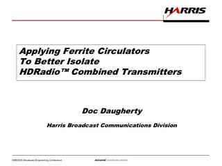
Applying Ferrite Circulators To Better Isolate HDRadio™ Combined Transmitters. Doc Daugherty Harris Broadcast Communications Division. 20,000 Watts. 20 Watts Cross-coupled. 200 Watts Forward. Why Need a Circulator? . Only -30dB isolation between antennas

E N D
Applying Ferrite CirculatorsTo Better IsolateHDRadio™ Combined Transmitters Doc Daugherty Harris Broadcast Communications Division
20,000 Watts 20 Watts Cross-coupled 200 Watts Forward Why Need a Circulator? Only -30dB isolation between antennas 20W cross-coupled signal into digital TX Apparent VSWR is 1.92:1, digital TX has VSWR trip
Circulator Basic Operation • A circulator is a non-reciprocal three-port device • RF energy entering port 1 is directed to port 2 • RF energy entering port 2 is directed to port 3 • RF energy entering port 3 is directed to port 1 • If RF energy enters port 1, it will leave port 2, and be attenuated by 25 to 30 dB at port 3 Port 2 Port 1 Port 3
Circulator Basic Operation • RF energy entering a circulator rotates clockwise and counterclockwise within the circulator • If RF energy enters port 1, the results are: • Clockwise rotation occurs at velocity V1 • Counterclockwise rotation occurs at velocity V2, which is twice that of V1 • The result it that the two rotations are in phase at port 2 (producing output) and cancel at port 3 (very little output) Port 2 Port 1 V1 Rotates Counterclockwise V2 Rotates Clockwise Port 3
Port 1RF Input fromtransmitter Port 2, antennaconnection,RF returning from antenna Port 3 Why Need a Circulator • In this slide, the circulator is configured as an isolator • RF energy from transmitter enters port 1 and is directed to port 2 and is transmitted by the antenna • Reflected or cross-coupled RF energy from antenna enteringport 2 is directed to port 3, where it is absorbed by the load • The isolator connection improves the transmitter’s isolation from reflected or cross-coupled energy arriving at port 2 by an additional 25 to 30 dB
Antenna Antenna 20,000 Watts Analog TX 20 Watts Cross-coupledFrom Analog Transmitter Circulator 200 Watts Forward Digital TX P 2 P 1 P 3 Isolator Load Why Need an Isolator? Circulator directs cross-coupled RF energy into its load.Digital TX does not see cross-coupled power.If isolation from port 3 to port 1 = 25 dB, digital TX sees 63 mW of cross-coupled power, its VSWR = 1.036.
Why Need an Isolator? • Spectrum display showing analog carrier, upper and lower IBOC sidebands, and the upper and lower sideband intermod (intermodulation) products • The intermod products result from PA non-linearity, by having both the analog signal and the IBOC sidebands simultaneously present in the PA AnalogCarrier USB Intermod LSB Intermod IBOC USB center freq IBOC LSB center freq
Why Need an Isolator? • Analog carrier freq = 102 MHz • IBOC USB range = 102.129 to 102.198 MHz • IBOC USB center freq =102.164 MHz • IBOC LSB center freq =101.836 MHz • Freq USB Intermod =3Fcar – 2F LSB center =306 – 203.672 =102.328 MHz • Freq LSB Intermod =3Fcar – 2F USB center =306 – 204.328 =101.672 MHz 102 MHz 102.328 MHz 101.672 MHz 102.164 MHz 101.836 MHz
Common Terminology • Isolator: • Circulator with an absorbing load at Port 3 • Isolator Load: • Terminating device matched to Port 3, to absorb any signal returning from Port 2 • Lumped Constant Circulator (Lumped Element): • Uses discrete capacitors and inductors • Smaller circulator at lower frequency • Narrower bandwidth and lower power capacity • Junction Circulator (Y-Junction, Y-Type, Distributive): • Larger, frequency-dependant size (Ferrite diameter near ½ wavelength) • Higher power capacity • Ferrite: • A ferrous material with a metallic crystalline structure • Insertion Loss: • Attenuation of a signal passing through a device (circulator = 0.15dB to 0.3dB) • Isolation: • Attenuated level of a signal appearing at an undesired location • Sometimes called Cross Coupling (circulator = 25dB – 30dB) • Return Loss: • Expression, in dB, of how attenuated a reflected signal is compared to the incident signal • Decibel expression of VSWR
Upper Pole Piece Upper Magnet Upper Ground Plane Upper Ferrite Disc Port 3 Port 2 Lower Ferrite Disc Lower Ground Plane Port 1 Center Conductor Lower Magnet Lower Pole Piece Internal Structure
Internal Structure • The magnetic field must travel vertically through the ground planes, ferrite discs, and center conductor of the circulator • Therefore, the upper and lower pole pieces are part of a steel box, not shown, which forms the enclosure of the circulator • The magnetic field travels vertically through the center of the circulator and Upper Pole Piece Upper Pole Piece Upper Magnet Upper Ground Plane Upper Ferrite Disc Center Conductor Lower Ferrite Disc Lower Ground Plane Lower Magnet completes its circuit through the Lower Pole Piece pole pieces and sides (not shown) of the circulator enclosure • When mounting the circulator, it is important to use aluminum or other non-magnetic hangers and supports and to use non-magnetic tools
Internal Structure • The center conductor, sandwiched between the upper and lower ground plane, forms a transmission line • The upper and lower ferrite discs are its dielectric (insulator) • The dielectric of the transmission line has both capacitive (permittivity) and magnetic (permeability) properties • The magnetic field strength, from the upper and lower permanent magnets, affect Upper Pole Piece Upper Pole Piece Upper Magnet Upper Ground Plane Upper Ferrite Disc Center Conductor Lower Ferrite Disc Lower Ground Plane Lower Magnet the permeability of the ferrite discs Lower Pole Piece • The permeability and permeability of the ferrite discs affect the inductance and capacity of the transmission line, which affects its impedance and velocity
Internal Structure • The impedance (Z) in ohms and the velocity (V) in meters per second of the transmission line are determined by the following formulas, where L = inductance in Henrys and C = capacity in farads per unit length of the transmission line Upper Pole Piece Upper Pole Piece Upper Magnet Upper Ground Plane Upper Ferrite Disc • It should be apparent that the operation of the circulator are greatly dependant on its parameters, such as Center Conductor Lower Ferrite Disc Lower Ground Plane Lower Magnet temperature, magnetic field strength, Lower Pole Piece composition and thickness of the ferrite discs, diameter of the circulator and other factors • These factors cause circulator to have a narrow frequency band and be power level and temperature dependant
Space Combining Methods • Separate & interleaved antennas • Space separation, between the analog and digital antennas • Antennas mounted on different towers • Digital antenna mounted above or below analog antenna on the same tower • Radiating element separation • The bays of the digital antenna are interleaved between the bays of the analog antenna
Antenna Antenna Analog TX Circulator Digital TX P 2 P 1 P 3 Isolator Load Separate Antenna Combining The problem with separate (or interleaved antennas is the cross-coupling between the two antennas, particularly from analog to digital -25dB 20kW This cross-coupling can cause VSWR trip in the digital transmitter, and, in smaller levels, can cause intermod products to be generated in the digital transmitter PA 63W Ref(3.55:1 VSWR) 200W (-20dB) 263W 63W to Isolator load
Interleaved Antenna Combining • The bays of an antenna are often spacedone wavelength apart • The bays of a second antenna can be positioned between the bays of the first antenna • Special design precautions must be taken: • To minimize cross-coupling between the bays of the two antennas • To ensure uniform (similar) patterns for each antenna Analog Antenna Digital Antenna Interleaved digital and analog antennas
Hybrid Combining Methods • Dual-feed antennas • 3 dB hybrid • Used to combine the analog and digital RF signals and feed them to a common antenna • The two hybrid outputs (90 degrees out of phase) feed the two antenna inputs, which also require a 90 degree phase separation • Master Antenna Systems • A single antenna is used to radiate RF signals from 2 or more transmitter systems, which are on different frequencies • Constant impedance filters are used to combine the analog and digital signals for each transmitter system, and then combine the outputs of the various transmitter systems into one or two common signal which will feed the antenna
Antenna Hybrid Combiner Analog TX Circulator Digital TX P 2 P 1 P 3 Isolator Load Typical Dual-feed Antenna 20.2kW 3dB 10.1kW 10.1kW 20kW -30dB / -15dBIsolation 20W / 632W Ref1.92:1 / Infinite 200W (-20dB) 220W / 832W 20W - 632W to Isolator load
Typical Dual-feed Antenna Dual feed antenna, one line went badThe hybrid splits the 100 W and 6 W reflections from the two lines between the two transmitters. Antenna Good linePf = 10.1kWVSWR = 1.05Pref = 6 W 20.2kW 3dB Bad linePf = 10.1kWVSWR = 1.22Pref = 100 W Hybrid Combiner Pref = 47 to 53W 20kW Analog TX -30dBIsolation 20W Ref1.92:1 Circulator 200W (-20dB) Digital TX P 2 P 1 220W P 3 20 W to Isolator load from hybrid isolation47 to 53 W to Isolator load from the bad and good line reflections Isolator Load
10 dB Hybrid Combining • Greatest power ratios • Transmitter may not be immune to antenna impedance match changes • Icing • Pressurization • Transmission line • Combiner reject load failure
Ideal System Match 10dB 20.2kw 1.05:1VSWR -32.3dB Return Loss 0.059%ReflectedPower= 12 W 22.2kW -35dBIsolation 4022W 7W1.12:1 2kW(-20dB)
Poor Antenna Match 727W Ref(90% hybrid split)-14.8dB1.44:1 10dB 20.2kW 1.50:1VSWR -14dB Return Loss 4%ReflectedPower=808 W 22.2kW -35dBIsolation 4022W 7W 2kW (-10dB) 2088w 81W Ref(10% hybrid split) 808W Ref Assuming 25 dB IsolationP3 to P1:Best case = 0.23 W (1.022) Worst case = 0.95 W (1.045) 74W Best case reflected 88W Worst case reflected
Open or Shorted Reject Load 10dB 402W Ref(-17.4dB1.31:1) 10% 22.2kW 4022W 3620W Ref 2kW(-10dB) 5620W 90% 3620W to Isolator load
Implementation Planning • When & where to use an isolator • When isolation less than 35dB • Shifting antenna match • TX protection from antenna or hybrid reject load failure • How to spec the circulator • Add forward digital power + coupled analog (return) power • Average power levels • Isolation spec of radiating elements or hybrid • Calculate isolation for separate antennas • Or, calculate possible catastrophic reflected powers
Implementation Planning • How to spec the isolator load • Load value for coupled analog power (plus 1.5 – 2x derating) • Or, load value for catastrophic failure protection • Isolator load requirements • Oil-filled • 100% duty cycle • Isolation rating of circulator is only as good as the load match • 30dB return loss @ frequency, +/- 200kHz, 0W – Max W • Size and weight considerations • Maybe somewhat large and VERY heavy
Installation • Mounting • Aluminum (or other non-magnetic) hangers/support • Stainless Steel securing hardware • Away from transformers and fans • Non-magnetic tools • Handling • Avoid shocks and vibration • Isolator load location • Away from circulator to reduce heat • Fan • Can help cool the load, if needed
Initial Turn-On • Ramp power up • Allow to warm-up • Alignment • Adjust for least VSWR at digital TX • Line matching transformer at PA output? • Measurements with spectrum analyzer • 2nd harmonic • Filter needed?
Operation • Normal case temperatures • Ambient up to 150°F • Abnormal operation • Too hot: Isolation degrades, excessive reflected power back to PA, PA parameters change, or PA damaged • Too cold: Input impedance match degrades, changes PA parameters • High humidity • Shock/Vibration • External or internal changes
Checklist • Circulator: • Forward digital power, plus… • Coupled analog power • Typical coupling (include possible VSWR) • Or, worst case (catastrophic) • Isolator load rating: • Coupled analog power • Typical coupling (include possible VSWR) • Or, worst case (catastrophic) • Interior climate: • Check manufacturer temperature and humidity ratings • Location & mounting • May be heavy and requires non-magnetic support hardware • How, what & where to monitor whole system • As many RF couplers as possible • Temperatures • Alignment • Line matching transformer • 2nd harmonic filter?
New Developments • More manufacturers • 5kW broadband (88 to 108 MHz) models • N+1 transmitter • Single circulator for separate IBOC combiners • VERY High power circulators (25kW - 45kW) • Provide high VSWR protection for analog transmitters • Reduce IM products of analog transmitter