Using Module Compiler to build FPGA Structures
180 likes | 319 Views
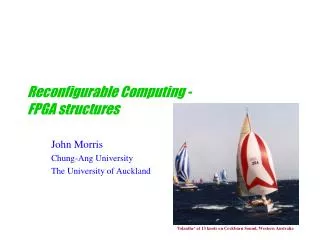
Using Module Compiler to build FPGA Structures. Seyi Ayorinde ECE 6505. Outline. Architectures FPGA Look-Up Table (LUT) Configurable Logic Block (CLB) Switch Box Using Module Compiler Approach Challenges. Architecture - FPGA.

Using Module Compiler to build FPGA Structures
E N D
Presentation Transcript
Using Module Compiler to build FPGA Structures SeyiAyorinde ECE 6505
Outline • Architectures • FPGA • Look-Up Table (LUT) • Configurable Logic Block (CLB) • Switch Box • Using Module Compiler • Approach • Challenges
Architecture - FPGA http://chipdesignmag.com/images/articles/16/zeidman_figure2.gif
Architecture – CLB http://www.eecg.utoronto.ca/vpr/images/pl_ble_internals.jpg For the purposes of this project, 1 BLE = 1 CLB (no clustering)
Architecture – Connectivity to Interconnect http://www.eecg.toronto.edu/~vaughn/challenge/Fc.gif
Architecture – Switch Matrix http://www.eecg.toronto.edu/~vaughn/challenge/switch_box.gif
Project Architecture • 100 CLBs • 10 x 10 Array • 4-Input LUTs • No Clustering • Channel Width – 4 • Reconfigurable Switch – Mux
Approach • Module Compiler – Relative Placement • Places portions of the design in specific areas relative to each other • Uses a grid of rows and columns • (0,0) is bottom left corner
Acronyms • HC and VC – Horizontal and Vertical Channels • SM – Switch Matrix • CLB – Configurable Logic Block
Approach • Code has been written to: • Create and place CLBs • Create and place HCs and VCs • Create and place SMs while connecting to HCs and VCs • Connect CLB Output to each channel • Connect CLB Input to each channel • Code needs to be written to: • Create and place I/O Blocks
Possible Issues • MCL Code • Demux function for connecting signal to multiple signals • If/else structure • Wire Directives (making sure vertical wires are vertical, etc.)
(Immediate) Future Work • Add I/O Blocks • Debug Code
Deliverables • MCL Code • Other MC Outputs • Layout file, Report Files, etc. • VHDL Code (Output of Module Compiler) • Schematic View • Layout (?) • Analysis of MC