Download
1 / 19
250 likes | 471 Views
Learn about Pulse Doppler Radar, Doppler Frequency Shift, Moving Objects Detection, Cancelling Techniques, Doppler Spectrum, Noise, and more.

E N D
Outline • More on Pulse Doppler Radar • Finding Doppler Frequency Shift • Determination of Moving/Stationary Objects on A-Scope and PPI • Use of Single and Double Delay Line Cancellers • Blind Speeds • Received Signals from Precipitation • Signal Sampling and Power Spectrum • Doppler Spectrum • Mean Doppler Velocity and Doppler Spectrum Variance • Radar Noise
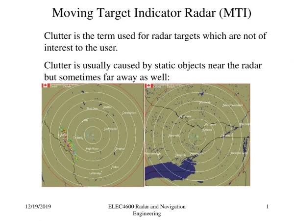
MTI vs. Pulse Doppler Radars • Both distinguish moving objects from stationary objects by looking at the Doppler Frequency shift. • MTI (moving target indication) radars • Typically operate with ambiguous velocity measurements (blind speeds), but with unambiguous range measurements • Pulsed Doppler Radars • PRF usually high enough to operate with unambiguous Doppler measurements but with ambiguous range measurements
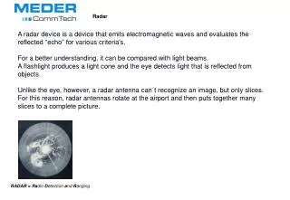
Operation Reference signal is sent Signal echo is measured Difference between signals is calculated to find Doppler frequency shift
Determining Moving Objects From A-scope • A-scope is a display of echo amplitude vs. time • Superposition of echoes can be helpful in separating moving objects from stationary object • “Butterfly Effect”
Echoes signals of fixed clutter have got the same amplitude pulse to pulse and can be cancelled:magenta: output of the phase-detector (actually period)green: output of the memory (delayed period)blue: cancelled video
Determination of Moving Objects on PPI • PPI (plan position indicator) • Angle vs. Range display • Different method must be utilized on PPI – Delay line canceller
Single Delay Line Canceller Signal delay T=1/PRF Output of canceller is a cosine wave at the Doppler frequency Amplitude of output is a function of the Doppler frequency and T
Frequency Response of Single Delay Line Canceller • Response is zero when Target velocities that result in zero MTI response are called “blind speeds” Somewhat effective removal of clutter Double/Multiple cancellation more effective
Frequency Response of Delay Line Cancellers • Avoid blind speeds by making first blind speed greater than maximum radial velocity • Increase wavelength of signal propagated • Increase PRF • Low radar frequencies (large wavelength) require larger antenna size • High PRF results in Range Ambiguity! • Example: First blind speed 600 knots • Range (without ambiguity) = 130 nautical miles at 300 MHz or 13 nautical miles at 30 MHz • Trade off between range and velocity ambiguities • One solution is “Staggered PRF MTI”
Signal Sampling and Power Spectrum • Conversion from continuous time to discrete samples • Power Spectrum Density (PSD) • Describes power as a function of frequency • Fourier transform of the autocorrelation function, if it can be treated as a stationary process.
Doppler Spectrum • Backscattered power received as a function of Doppler frequency, or velocity • Describes the echo of a contributing region of signal • Function given as S(f), S(V), or S(ω); • Doppler Spectrum Spread • Large difference of size means large spread • Turbulence • Air motion across beam
Average Power • Average Power can be given in terms of Doppler velocity or frequency
Mean Doppler Velocity and Doppler Spectrum Variance • A more convenient measure of the Doppler spectrum spread can be given by the variance, σ2 • Found from mean Doppler velocity
Radar Noise • Thermal Noise • Thermal excitation of electrons in electrical components • Always exists in any electrical system • Totally random, but has a normal distribution • Coherent Averaging or Stacking • Quantization Noise • Quantization noise due to rounding errors • Dithering • Coherent Noise • Coherent radar systems use a master oscillator to derive frequencies and timing signals • Leakage from these signals into the receiver causes noise • 0/π Phase Modulation