Download
1 / 23
230 likes | 493 Views
Design and Application of Near Infrared Tunable Filter for ATST and NST Doctoral Thesis Proposal by Jun Ma February, 2005. Contents. Introduction Related Work Achromatic Waveplate Layered medium Infrared Imaging Magnetograph system (IRIM)

E N D
Design and Application of Near Infrared Tunable Filter for ATST and NST • Doctoral Thesis Proposal • by • Jun Ma • February, 2005
Contents • Introduction • Related Work • Achromatic Waveplate • Layered medium • Infrared Imaging Magnetograph system (IRIM) • Magnetic structures of light bridges and umbral dots • Tasks • Timeline
(3) Magnetograph System • Measuremetn B
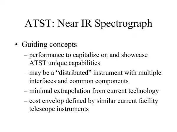
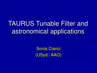
(1) Infrared Observation • Advantages of IR observation • Strong Zeeman splitting • Detecting weaker fields • Optical opacity reaches minimum at 1.6 micron • Earth atmosphere • Scattering light • Disturbance • Seeing condition is better • Instrumental difficulties in IR • Detectors • Optical components (for filter) • Polarizer, LC, coatings • Tunability FTS Observation of umbral Stokes profiles: I & V. Field Strength is roughly around 300 Gauss. Rueedi, et al., 1994
New Solar Telescope Big Bear Solar Observatory 1.6-meter ATST • (2) ATST & NST A substitution of current 65cm telescope. It will be the largest ground based solar telescope before the construction of ATST (2006). Advanced Technology Solar Telescope (ATST) National Solar Observatory Based on the theoretical models, the magnetic features on the Sun have spatial scales about 30km. This corresponds to a 4-meter aperture at 630.2 nm, an important line for most polarimetry studies. Lift time spans 3~4 decades. My thesis project is supported by ATST “near infrared tunable filter system” project. NST
(4) NIR Narrow band tunable filter and image-based magnetograph Polarization Modulation (one example): Baur & Elmore, “Stokes II – A new polarimeter for solar observation”, 1980 • Design tasks: • Match FWHM of Lyot with the FSR of FPI; • Suppress the off band transmission – stray light.
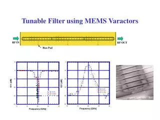
(5) Lyot Filter - Structure • Convolve of FPI/Lyot • Mention FPI 1.56 m Birefringent filter, designed by Dr. J. Wang. Bandpass = 2.2 Å ; LC tuning; normal-wavelates. Used in the observation at SacPeark, in Dec. 2004 Tunable Laser testing of 1.56m birefringent filter. Proceeded at Cambridge Research Incorporated (CRi), March, 2004
Contribution • Achromic • Calibr • Application
Lyot Filter - Tuning Tunable Birefringent Filter design in J. Wang’s paper. without achromatism consideration, i.e., working at single wavelength. Wavelength tuning v.s. rotation angle of waveplate A linear relation. Simulated with Jones matrix method in MATLAB. Voltage count on LC’s v.s. retardation [Courtesy CRi, Inc.] Non-linear; oracle function
Contents • Introduction • Related Work • Achromatic Waveplate • Layered medium • Infrared Imaging Magnetograph system (IRIM) • Magnetic structures of light bridges and umbral dots • Tasks • Timeline
Questions needs answer in final thesis • Waveplates ( layered birefringent crystals) • More layers achromatic waveplate • Incident angles • Propagation of polarization modes • Lyot filter • Tuning & Instrumental Errors • LC properties • Calibration • Filter system • Synchronization • Light bridges and umbral dots • Field strength and distribution • Motion • Energy transport mechanism
One idea of making achromatic waveplate ? How about different layers of different birefringent materials? How many do we need?
Preliminary numerical simulation (1) [ Left Panel ] Retardance error plotted from Title’s paper. 1975 – A.M. Title, “Improvement of Birefringent Filters 2: Achromatic Waveplates”, J.O.S.A., 1975 [ Right Panel ] Retardance error plotted from new design. 2004 – J. Ma, J. Wang, W. Cao, C. Denker, H. Wang. “Near Infrared (NIR) Achromatic Phase Retarder”, SPIE, Oct 2004 • Result shown here is half-waveplate. • The achromatic range on the left is around 200 nm ; on the right, achromatic range is 700 nm . Also, it should be noticed that the error tolerance is defined in different sense.
Testing of three-layer achromatic waveplate Transmission profile (not retardance profile). Courtesy Nanjing Institution of Astronomical Instrumentation. Testing cases: 1) Half awp sandwiched by parallel aligned linear polarizers 2) Two quarter awp sandwiched by parallel aligned linear polarizers Blue curve: achromatic waveplate Red curve: normal waveplate Yellow curve: stray light of the two linear polarizers
Calibration of Lyot filter, December, 2004 Calibration of 1.56 micron Lyot filter from data of December, 2004. FWHM ~ 2.1 angstrom CRi calibration
Calibrations • Calibration of achromatic waveplates. • Calibration of tunable birefringent fitler. • Data analysis of the calibration in Dec 2004, NSO • Calibration of high resolution tunable filters • Lookup-table for Voltage on LC’s of Lyot filter • Lookup-table for FPI bandpass shifting • Automatic calibration procedure instead of lookup-tables • CLIPS – C Language Integrated Production System • The Artificial Intelligence Section at NASA’s Johnson Space Centre • Expert system / An Inference Engine of Logics • Prototype – 1984; Open to public – 1986
Data Analysis: Light Bridges and Umbral Dots • Field Strength measurement • The Zeeman splitting between two circular polarizations • The magnitude of the linear polarization gives some hint on the inclination of the field • VMG is needed in order to get the true vector field: polarization modulator • Field distribution • The characteristics of the field strength distribution within interested area: boundaries • Comparison between these characteristics with quiet sun granulations • Field evolution • Is it possible to have velocity map? • Time evolution of light bridges and umbral dots • High spatial resolution is required
Quiet sun granular (6) Light Bridges and Umbral Dots L.B. [ Dec. 2, 2004, NSO-SacPeak ] NOAA 10706 FOV: 120” 120” Filtergram observed @ 1.56 m FWHM = 2.2 Å Processed with flat-field correction. The dynamic process of these two interests me more. How do they evolve? Umbral dots pores umbra Umbral dots penumbra 120” L.B. 120”
First-light of IRIM of BBSO Dec. 2004 Lyot + FPI Centred at 1.56 micron Bandwidth ~0.15 angstrom Seeing condition got worse during this period compared with the observation with Lyot filter one day before. The fringe pattern comes probably from FPI, since it didn’t appear in Lyot observation. However, it could come from other optics as well, since the optical setup were quite different. Again, a movie might be more interesting. Also, since the filter system was used to scan the neighbouring spectral range, the Zeeman splitting of the FeI line might be derived from this time sequence of images. Data process hasn’t been done yet.
Contents • Introduction • Related Work • Achromatic Waveplate • Layered medium • Infrared Imaging Magnetograph system (IRIM) • Magnetic structures of light bridges and umbral dots • Tasks • Timeline
The End Newark, NJ February, 2005