Acousto optic modulators
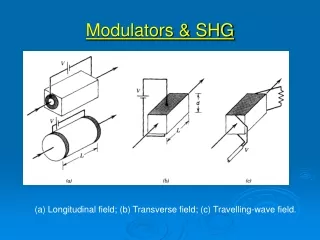
Acousto optic modulators. Additional details relevant for servos. AOM crystal/glass. Refractive index variations due to sound waves. Sound absorber (suppress reflections). Aperture. Deflected beam. Input laser beam. l. v. Undeflected beam. Sound transducer ex: LiNbO 3. RF signal

Acousto optic modulators
E N D
Presentation Transcript
Acousto optic modulators Additional details relevant for servos
AOM crystal/glass Refractive index variations due to sound waves Sound absorber (suppress reflections) Aperture Deflected beam Input laser beam l v Undeflected beam Sound transducer ex: LiNbO3 RF signal ~ 1 Watt 40 MHz AOM = acousto optic modulator • AOM = acousto optic modulator (or deflector) • RF signal converted to sound waves in crystal • Use fast piezo-electric transducer like Li NbO3 • Sound waves are collimated to form grating • Bragg scatter from grating gives deflected beam • can separate from original • Problem with AOM -- weak link • Sound takes time to travel from transducer to laser beam • Time delay: tD = l / v -- acts like multi-pole rolloff • (phase shift increases with frequency)
output Integer wavelengths input vs vs Grating planes Thick gratings • Many layers • Reflectivity per layer small Examples: • Holograms -- refractive index variations • X-ray diffraction -- crystal planes • Acousto-optic shifters -- sound waves • grating spacing given by sound speed, RF freq. Bragg angle: dL = 2d sin qB = nl d = vsound / fmicrowave
Typical AOM materials Glass AOM • sound speed 6 km/sec • time delay 160 nsec / mm distance from transducer • 40 MHz drive --> 150 mm fringe spacing • for 0.6 micron light, Bragg angle = 2 mrad = 0.1 degree Table 2. Acousto-Optic Materials Material Chemical Spectral range Figure of merit M2 Bandwidth Typical Index of Refraction Acoustic Velocity formula(m m) (10- 15m2/W) (MHz) drive power (W) (m/sec) Fused silica/quartz SiO2 0.3 - 1.5 1.6 to 20 6 1.46 (6343 nm)5900 Gallium arsenide GaAs 1.0 - 11 104 to 350 1 3.37 (1.15 mm)5340 Gallium phosphide GaP 0.59 - 1.0 45 to 1000 50 3.31 (1.15 mm)6320 Germanium Ge 2.5 - 15 840 to 5 50 4.0 (10.6 mm)5500 Lead molybdate PbMoO4 0.4 - 1.2 50 to 50 1 - 2 2.26 (633 nm)3630 Telluriumdioxide TeO20.4 - 5 35 to 300 1 - 2 2.26 (633 nm)4200 LithiumniobateL6Nb030.5-27> 30050-1002.20 (633nm)6570
AOM driver • Fixed frequency: 40 MHz • Can change amplitude (power) with input voltage • does not change Bragg angle • need voltage controlled oscillator (VCO) to change angle • RF power determines • sound wave amplitude, • density change, • refractive index modulation depth, • diffracted light power Saturation effects • Bragg diffraction saturates • deflected beam power diffracted back into undeflected beam • Acoustic wave saturates • Index modulation depth no longer linear in microwave power • higher order diffracted beams
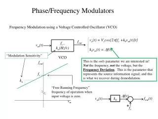
Low-pass filter I Vin =V0 cos(2 pf t) Vout R C I Gain response logVin knee log(Vout) f = 1 / 2 p t Phase response log(f ) log(f ) phase voltage -90 degrees 0 degrees f = 1 / 2 p t time Low pass filter • Above knee phase shift is constant -- amplitude rolls off Response on oscilloscope
Phase response f = 1 / 2 ptD log(f ) 0 degrees phase -90 degrees -180 degrees AOM crystal/glass -270 degrees Refractive index variations due to sound waves Deflected beam Input laser beam l v Undeflected beam RF signal ~ 1 Watt 40 MHz Time delay • Amplitude is constant • When 1/f approaches delay time • Phase increases rapidly • Phase shift linear in f • Grows exponentially on semi-log plot • Cannot compensate with lead Response on oscilloscope voltage time td = l/v