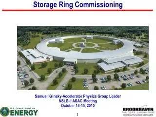
Storage Ring - Conventional Facilities Interfaces
Storage Ring - Conventional Facilities Interfaces. Erik Johnson, Accelerator Systems Interface Manager Accelerator Systems Advisory Committee Meeting July 17-18, 2008. Storage Ring to Conventional Facilities?. Louis Henri Sullivan Architect (1856 – 1924). Form ever follows function.

Storage Ring - Conventional Facilities Interfaces
E N D
Presentation Transcript
Storage Ring - Conventional Facilities Interfaces Erik Johnson, Accelerator Systems Interface Manager Accelerator Systems Advisory Committee Meeting July 17-18, 2008
Storage Ring to Conventional Facilities? Louis Henri Sullivan Architect (1856 – 1924) Form ever follows function
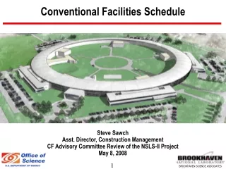
NSLS-II : Form following function A-301, 80% Title II
And how it got that way….. 9 June 2008 Coordination Meeting
Overview of SR-CF Interfaces • Identify Interfaces • Specifications for the storage ring set building parameters and interfaces • Some examples • Ratchet wall coordination • Process Utilities • Storage Ring Openings • Coordination with CF Design (80% Title II review) • Conventional Facilities Functional Requirements • Where you can find interface information
Example Conventional Facilities Coordination Storage Ring Ratchet Wall Specification • ASD, CFD, ESH and XFD all interested stakeholders • Iterative development of requirements with stakeholders • Document agreements and specifications • Coordination with A/E (HDR) and CFD to implement
Technical Stakeholders ESH • Tunnel is first and foremost a radiation enclosure • Relationship of ring with enclosure impacts on shielding performance Accelerator Systems • Tunnel interacts with (constrains) storage ring configuration • Provides platform for mounting of equipment supporting operation of the accelerator Experimental Facilities • Interface between machine and user beamline • Ratchet wall interacts with (constrains) beamline configuration Conventional Facilities • Tunnel is substantial portion of construction activity • Design interacts with (constrains) other building systems 29 January 2008 Interface Meeting
Ratchet Wall Design Documents ESH documents • Bulk Shielding Requirements for Final Design of NSLS-II Accelerator Enclosures, Job & Casey, 2008 Jan 25 • Final Design Parameters and Beam Loss Assumptions for Shielding Calculations of NSLS-II Accelerator Enclosures, Job & Casey, 2008 Jan 25 • Shield vs distance 1.XLS (translation of shielding requirements for ratchet wall design by PK Job) Engineering documents • Drawing SR-DG-1003-1-15-08 29 January 2008 Interface Meeting
Ratchet Wall Specification • See dwg for layout details • Normal concrete walls except injection area (HD from 28B to 30B) • Ratchet walls 1.37 m thick • Source to outside wall distances – • Source Wall face CL to Inboard • Low Beta ID 26.7 m 500 mm • 3PW (low beta) 26.2 m 800 mm • Bend (low beta) 25.7 m 722 mm • High Beta ID 28.4 m 500 mm • 3PW (high beta) 24.9 m 800 mm • Bend (high beta) 24.4 m 728 mm 29 January 2008 Interface Meeting
Ratchet Wall Aperture Not yet specified but consider variations • Variability in lattice design • Change of 200 mm in dipoles shifted low beta inboard 16 mm, high beta outboard 5mm, make ‘budget’ of 20 mm • Concrete placement • Nominal specification is variability of 25 mm for vertical lines • Decker distortion (offset 5 mm outboard) • Canting (consider cant dipole to dipole, 1.75 mrad) • Outboard line at wall 64 mm outside of CL • Inboard line at wall 35 mm inside of CL • Extracted fan (nominally 3 mrad) • About 75 to 80 mm width at wall • EF specifies 8” diameter pipe (200 mm full aperture) Outboard: 20+25+64+100+ 209 mm (say 8 1/4”) Inboard: 20+25+35+100=180 mm (say 7 1/8”) Propose 16” clear opening, 8.5” to outboard, 7.5” to inboard Full width shelf inside for lead 250 mm thick 29 January 2008 Interface Meeting
High beta front end 29 January 2008 Interface Meeting Schematic, but suggests about 1.5 meters could be appropriated from front end Would have impact on FOE layout and ratchet wall doors
Revised Ratchet Wall Specification • See dwg for layout details • Normal concrete walls except injection area (HD from 28B to 30B) • Ratchet walls >1.37 m thick • Source to outside wall distances – Source Wall face CL to Inboard • Low Beta ID 25.5 m 330 mm • 3PW (low beta) 25.0 m 716 mm • Bend (low beta) 24.5 m 643 mm • High Beta ID 26.7 m 330 mm • 3PW (high beta) 23.7 m 696 mm • Bend (high beta) 23.2 m 626 mm 6 February 2008 Interface Meeting
80% Title II Drawing A-401 High Beta distance from 6 Feb meeting: 26.7 m
NSLS-II Process Utility Loads Revision 1
Gaseous Nitrogen System Inj Cryo RF SB4 SB3 SB2 SB1 SB5 Port B Port A SR Tunnel LOB 4 gN2 LOB 3 LOB 2 LOB 1 LOB 5 CFD Scope ASD Scope x6 Tunnel manifold: 8 taps/cell typical
Storage Ring typical single cell Port B Port A Use Frequency Components Intermittent Front End Seldom Purge gas source Seldom ID Isolation valve Frequent Beamline supply Use Frequency Components Seldom BM Photon Shutter Seldom Slow Gate Valve Intermittent Photon Shutter Seldom Fast Gate Valve Intermittent Safety Shutter Beamlines Nominal use 0.4 cfm each 2/cell, 12/pentant
Storage Ring Tunnel Openings Example Openings 50% Title II Drawing, A-101K
Storage Ring Tunnel Openings http://groups.nsls2.bnl.gov/acceleratorsystems/interface/Lists/SR Openings
Conduit layout CD-type conduit C A D B C 120 total connecting Storage ring tunnel and mezzanine A D B A-type conduit LT Electrical; George Ganetis
Comments on 80% Title II Submission http://groups.nsls2.bnl.gov/acceleratorsystems/interface/Consolidation CF Design Comments for ASD
Conventional Facilities Requirements http://groups.nsls2.bnl.gov/acceleratorsystems/interface/Lists/Conventional Facilities Requirements
SR Tunnel Functional Requirements http://groups.nsls2.bnl.gov/acceleratorsystems/interface/Lists/Conventional Facilities Requirements
Accelerator Systems SharePoint http://groups.nsls2.bnl.gov/acceleratorsystems
ASD Interface development SharePoint http://groups.nsls2.bnl.gov/acceleratorsystems/interface
Summary of SR-CF Interfaces • Identify Interfaces • Active and ongoing effort to identify and refine interface definitions • Some example interfaces • Illustrated some of the AS-CF interface definition to date • Where you can find interface information • SharePoint site references (Libraries, Lists) • RSI Documentation (BNL and HDR) • Look ahead • Continuing elaboration of interface specifications as design evolves • Improved delivery and accessibility of interface information