LMC 30
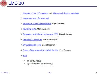
LMC 30. run 090813.21. Heat pulse. 1.9 K, 0 T, 7.5 kA. Calculated temperature along the bus (1.9 K, 2 T, 6000 A). U=100-150 mV: switch off current during test. Correlation experiment vs. calculation. Conclusion on ‘Analysis FRESCA test’

LMC 30
E N D
Presentation Transcript
LMC 30 LPC
run 090813.21 Heat pulse 1.9 K, 0 T, 7.5 kA A. Verweij, TE-MPE. 30 Sept 2009, LMC meeting
Calculated temperature along the bus (1.9 K, 2 T, 6000 A) U=100-150 mV: switch off current during test A. Verweij, TE-MPE. 30 Sept 2009, LMC meeting
Correlation experiment vs. calculation A. Verweij, TE-MPE. 30 Sept 2009, LMC meeting
Conclusion on ‘Analysis FRESCA test’ • The simulation code (QP3) is now validated!!! There is a good agreement between experiment and calculations for the voltage signals, the temperatures and the thermal runaway times (for 1.9 K and 4.3 K and currents from 2-12 kA). The quench currents of more than 50 test cases can be simulated with an accuracy better than a few hundred Amps. • To fit the calculations to the experiments, the cooling to helium had to be reduced by about 15% as compared to previous assumptions, possibly due to the presence of film boiling. A separate thermal test by David Richter will be done in coming week. A. Verweij, TE-MPE. 29 Sept 2009, TE-TM meeting
RB: case 2 (quench in GHe environment) A. Verweij, TE-MPE. 30 Sept 2009, LMC meeting
Summary table of maximum allowable additional resistance for RB circuit with tau=50 s. Safety margin not included For info A. Verweij, TE-MPE. 30 Sept 2009, LMC meeting
Conclusion on ‘Safe current calculations’: • After analysis of the ‘FRESCA 61 mW test’ and taking RRRbus=100, RRRcable=120, tauRB=50 s, tauRQ=10 s, and assuming a maximum Raddit=90 mW, one can conclude that operating at 3.5 TeV is safe. Operation at 5 TeV seems risky, especially because at this energy a magnet quench could propagate quickly to the interconnect by means of normal zone propagation in the bus. • Better estimates of: • Thermal propagation through the M1-M3 lines, • RRRcable (tests are ongoing in MSC group), • Heat flow through the bus (and interconnect) insulation (test planned for this week) • are important to further improve the accuracy of the calculations of the ‘safe current’. • A few more FRESCA tests in a ‘machine-type layout’ are planned for the coming months and will give additional experimental data for better understanding of the thermal processes. Samples containing low RRRbus (100-150) and Raddit with values between 20 and 50 mW are most important. A. Verweij, TE-MPE. 30 Sept 2009, LMC meeting