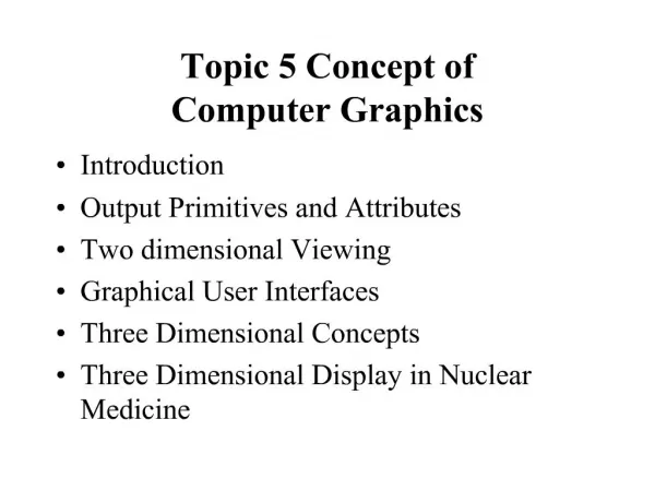
Exploring Polygon Meshes in Computer Graphics
Understand the components and challenges of polygon mesh modeling in computer graphics, including vertices, edges, normals, and textures. Learn about sweep objects, sweeps along paths, limitations of polygons, spatial enumeration, and adaptive voxel resolution.

Exploring Polygon Meshes in Computer Graphics
E N D
Presentation Transcript
CS559: Computer Graphics Lecture 24: Shape Modeling Li Zhang Spring 2010
Polygon Meshes • A mesh is a set of polygons connected to form an object • A mesh has several components, or geometric entities: • Faces • Edges • the boundary between faces • Vertices • the boundaries between edges, • or where three or more faces meet • Normals, Texture coordinates, colors, shading coefficients, etc • What is the counterpart of a polygon mesh in curve modeling?
struct Vertex { float coords[3]; } struct Triangle { GLuint verts[3]; } struct Mesh { struct Vertex vertices[m]; struct Triangle triangles[n]; } OpenGL and Vertex Indirection glEnableClientState(GL_VERTEX_ARRAY) glVertexPointer(3, GL_FLOAT, sizeof(struct Vertex), mesh.vertices); glBegin(GL_TRIANGLES) for ( i = 0 ; i < n ; i++ ) { glArrayElement(mesh.triangles[i].verts[0]); glArrayElement(mesh.triangles[i].verts[1]); glArrayElement(mesh.triangles[i].verts[2]); } glEnd();
Normal Vectors in Mesh • Normal vectors give information about the true surface shape • Per-Face normals: • One normal vector for each face, stored as part of face (Flat shading) struct Vertex { float coords[3]; } struct Triangle { GLuint verts[3]; float normal[3]; } struct Mesh { struct Vertex vertices[m]; struct Triangle triangles[n]; }
Normal Vectors in Mesh • Normal vectors give information about the true surface shape • Per-Vertex normals: • A normal specified for every vertex (smooth shading) struct Vertex { float coords[3]; float normal[3]; } struct Triangle { GLuint verts[3]; } struct Mesh { struct Vertex vertices[m]; struct Triangle triangles[n]; }
Other Data in Mesh • Normal vectors give information about the true surface shape • Per-Vertex normals: • A normal specified for every vertex (smooth shading) • Per-Vertex Texture Coord struct Vertex { float coords[3]; float normal[3]; float texCoords[2]; } struct Triangle { GLuint verts[3]; } struct Mesh { Vertex vertices[m]; Triangle triangles[n]; }
Other Data in Mesh • Normal vectors give information about the true surface shape • Per-Vertex normals: • A normal specified for every vertex (smooth shading) • Per-Vertex Texture Coord, Shading Coefficients struct Vertex { float coords[3]; float normal[3]; float texCoords[2], diffuse[3], shininess; } struct Triangle { GLuint verts[3]; } struct Mesh { Vertex vertices[m]; Triangle triangles[n]; }
Issues with Polygons • They are inherently an approximation • Things like silhouettes can never be perfect without very large numbers of polygons, and corresponding expense • Normal vectors are not specified everywhere • Interaction is a problem • Dragging points around is time consuming • Maintaining things like smoothness is difficult • Low level representation • Eg: Hard to increase, or decrease, the resolution • Hard to extract information like curvature
In Project 3, we use Sweep Objects • Define a polygon by its edges • Sweep it along a path • The path taken by the edges form a surface - the sweep surface • Special cases • Surface of revolution: Rotate edges about an axis • Extrusion: Sweep along a straight line
General Sweeps • The path maybe any curve
General Sweeps • The path maybe any curve • The polygon that is swept may be transformed as it is moved along the path • Scale, rotate with respect to path orientation, … Cube Twisted Cube
General Sweeps • The path maybe any curve • The polygon that is swept may be transformed as it is moved along the path • Scale, rotate with respect to path orientation, … • One common way to specify is: • Give a poly-line (sequence of line segments) as the path • Give a poly-line as the shape to sweep • Give a transformation to apply at the vertex of each path segment • Texture Coord? • Difficult to avoid self-intersection
Klein Bottle Torus Klein Bottle
Mobious Strip Non-orientable surfaces
Spatial Enumeration • Basic idea: Describe something by the space it occupies • For example, break the volume of interest into lots of tiny cubes • Data is associated with each voxel (volume element), binary or grayscale. • Works well for things like medical data (MRI or CAT scans, enumerates the volume)
Spatial Enumeration • Basic idea: Describe something by the space it occupies • For example, break the volume of interest into lots of tiny cubes • Data is associated with each voxel (volume element), binary or grayscale. • Works well for things like medical data (MRI or CAT scans, enumerates the volume) • Problem to overcome: • For anything other than small volumes or low resolutions, the number of voxels explodes • Note that the number of voxels grows with the cube of linear dimension
Octrees (and Quadtrees) • Build a tree for adaptive voxel resolution • Large voxel for smooth regions • Small voxel for fine structures • Quadtree is for 2D (four children for each node) • Octree is for 3D (eight children for each node)
Rendering Octrees • Volume rendering renders octrees and associated data directly • A special area of graphics, visualization, not covered in this class • Can convert to polygons: • Find iso-surfaces within the volume and render those • Typically do some interpolation (smoothing) to get rid of the artifacts from the voxelization
Rendering Octrees • Typically render with colors that indicate something about the data Surface rendering with color coded brain activity One MRI slice
Parametric surface • Line Segments (1D) -> polygon meshes (2D) • Cubic curves (1D) -> BiCubic Surfaces (2D) • Bezier curve -> Bezier surface
Bilinear Bezier Patch • Define a surface that passes through a, b, c, d? Looks familiar?
Biquadratic Bezier Patch • Define a surface that passes a 3x3 control lattice. v p(u,0) = (1-u)2 p00 + 2(1-u)u p10 + u2 p20 p(u,1) = (1-u)2 p01 + 2(1-u)u p11 + u2 p21 u p(u,2) = (1-u)2 p02 + 2(1-u)u p12 + u2 p22 p(u,v) = (1-v)2 p(u,0)+ 2(1-v)v p(u,1)+ v2 p(u,2)
Bicubic Bezier Patch • 4x4 control points? • Demo: http://www.nbb.cornell.edu/neurobio/land/OldStudentProjects/cs490-96to97/anson/BezierPatchApplet/index.html • Connecting Bezier Patches, demo on the same page.
De Casteljau algorithm in 2D p100(u,v) = Bilinear(p00, p10, p01, p11; u, v) p101(u,v) = Bilinear(p01, p11, p02, p12; u, v) p110(u,v) = Bilinear(p10, p20, p11, p21; u, v) p111(u,v) = Bilinear(p11, p21, p12, p22; u, v) p100(u,v) = Bilinear(p00, p10, p01, p11; u, v)
General Formula for Bezier Patch • If we have contronl points pi,j on a m by n lattice, • Properties • Invariant to affine transform • Convex combination, • Used for intersection
General Formula for Bezier Patch • If we have contronl points pi,j on a m by n lattice, • Surface Normal
Issues with Bezier Patches • With Bézier or B-spline patches, modeling complex surfaces amounts to trying to cover them with pieces of rectangular cloth. • It’s not easy, and often not possible if you don’t make some of the patch edges degenerate (yielding triangular patches). • Trying to animate that object can make continuity very difficult, and if you’re not very careful, your model will show creases and artifacts near patch seams. • Subdivision Surface is a promising solution.
Subdivision Surface • From a coarse control mesh to smooth mesh with infinite resolution
Subdivision Curve We have seen this idea before Shirley, Figure 15.15, The limiting curve is a quadratic Bezier Curve RTR 3e, Figure 13.29, The limiting curve is a quadratic B-spline
Subdivision Curves: Approximating Initial (Control) Curve: For each iteration k+1, add two vertices between: Approximating: Limit curve is very smooth (C2), but does not pass through control points
Subdivision Curves: Interpolating Initial (Control) Curve: For each iteration k+1, add two vertices between: Interpolating: for 0<w<1/8, limit curve is C1, and passes through control points
Subdivision Curves: Interpolating • Handling Boundary Cases
Subdivision Surfaces Extend subdivision idea from curves to surfaces RTR, 3e, figure 13.32
Loop Subdivision • Regular vertex: valence = 6 • Irregular vertex: valence != 6 • Irregular vertices can only be initial vertices.
Loop Subdivision C2 for regular vertices C1 for irregular vertices
Limiting Surface • Position and tangent of a vertex of the limiting surface can be computed directly ∞
Sqrt(3) subdivision C2 for regular vertices C1 for irregular vertices
Sqrt(3) vs Loop • + slower triangle growth rate • + better for adaptive subdivision • Edge flipping adds complexity • Less intuitive at first few iterations