Programmable Interval Timer/Counter 8254 Overview
Learn about the 8254 Programmable Interval Timer with 3 independent 16-bit programmable counters, counting in binary/BCD for real-time clock and event counting applications. Understand its block diagram, I/O structure, and programming methods.

Programmable Interval Timer/Counter 8254 Overview
E N D
Presentation Transcript
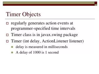
The 8254 Programmable Interval Timer • 3 independent 16-bit programmable counters • Counting in binary/BCD • Applications • Real-time clock • Event counter
8254 I/O • D7-D0: System data bus • CLK0: Clock for counter 0 • Gate0: Gate for counter 0 • CLK1: Clock for counter 1 • Gate1: Gate for counter 1 • CLK2: Clock for counter 2 • Gate2: Gate for counter 2 • A1-A0: Address select • 00: Counter 0 • 01: Counter 1 • 10: Counter 2 • 11: Control Register • Vcc: Power (+5V) • Ground: • RD: Read enable • WR: Write enable • CS: Chip select signal • OUT0: Output of counter0 • OUT1: Output of counter1 • OUT2: Output of counter2
Programming the 8254 • Each counter is programmed individually by writing • A control word • The initial count • Control word selects • Counter • Mode of operation • Type of operation (read/write) • Type of count (binary/BCD) • Program sequence 1: • PROGRAM CONTROL WORD 1 • PROGRAM CONTROL WORD 2 • PROGRAM LSB 1 • PROGRAM LSB 2 • PROGRAM MSB 1 • PROGRAM MSB 2 • Program sequence 2: • PROGRAM CONTROL WORD 1 • PROGRAM LSB 1 • PROGRAM MSB 1 • PROGRAM CONTROL WORD 2 • PROGRAM LSB 2 • PROGRAM MSB 2
8254 Modes of Operation • Mode 0: Events counter. • Mode 1: One shot pulse • Mode 2: Continuous pulses, one clock pulse wide • Mode 3: Continuous square-wave as long as Gate is 1 • Mode 4: Software triggered one-shot pulse • Mode 5: Hardware triggered one-shot pulse
Modes of Operation • Mode 0: Events counter (used for system time) • Mode 1: One shot pulse
Modes of Operation • Mode 2: Continuous pulses • Mode 3: Continuous square-wave
Modes of Operation • Mode 4: Software triggered one-shot pulse • Mode 5: Hardware triggered one-shot pulse