Download
1 / 18
180 likes | 204 Views
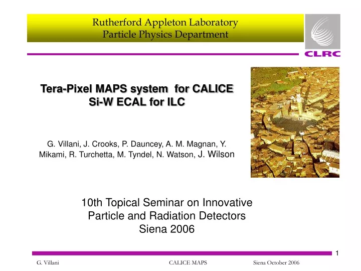
10th Topical Seminar on Innovative Particle and Radiation Detectors Siena 2006. Tera-Pixel MAPS system for CALICE Si-W ECAL for ILC. G. Villani, J. Crooks, P. Dauncey, A. M. Magnan, Y. Mikami, R. Turchetta, M. Tyndel, N. Watson, J. Wilson. ILC Calice description

E N D
10th Topical Seminar on Innovative Particle and Radiation DetectorsSiena 2006 Tera-Pixel MAPS system for CALICE Si-W ECAL for ILC G. Villani, J. Crooks, P. Dauncey, A. M. Magnan, Y. Mikami, R. Turchetta, M. Tyndel, N. Watson, J. Wilson
ILC Calice description • CALICE MAPS Concept, design and simulation results • Conclusions Outline
ILC operation • Exact ICL beam timing parameters not yet defined • Assume close to previous (“TESLA”) design • Beams collide rapidly within a quick burst (“train”) • Long dead time between trains • Worst case timing assumption as follows • Beam collision rate within train = 6.7 MHz, i.e. 150ns between collisions • Number of collisions within train = 14000, i.e. train is 2ms long • Train rate = 10Hz, i.e. 100ms between trains; 2% duty cycle • Rate of signals • ILC is not like LHC; rate of physics processes is small • Most collisions give nothing, but when reaction does happen, many adjacent channels will be hit • Expected rate not very well known; needs detailed simulation modeling • Assume average ~106 hits/pixel/crossing, which is ~0.005 hits/pixel/train TESLA 500GeV
CALICE ECAL description • CALICE has a baseline ECAL design • Sampling calorimeter, alternating thick conversion layers (tungsten) and thin measurement layers (silicon) • Around 2m radius, 4m long, 30 layers W and Si, total Si area including endcaps ~ 2×107cm2 • Silicon sensor detectors in baseline are diodepads • Pad readout is analogue signal; digitized by Very Front End (VFE) ASIC mounted next to sensor • Average dissipated power 1 W/mm2 • Pad size between 1.0×1.0and0.5×0.5cm2; total number of pads around 20 - 80M • Mechanical structure • Half of tungsten sheets embedded in carbon fiber structure • Other half of tungsten sandwiched between two PCBs each holding one layer of silicon detector wafers • Whole sandwich inserted into slots in carbon fiber structure • Sensitive silicon layers are on PCBs ~1.5m long× 30cm wide
CALICE ECAL description Si wafers ECAL baseline design
CALICE MAPS concept • Baseline design largely unaffected by use of MAPS instead of diode pads • Potential benefits include: • Reduced PCB section for MAPS Decrease in Molière radius Increased resolution • Increased surface for thermal dissipation • Less sensitivity to SEU • Cost saving (CMOS standard process vs. high resistivity Si for producing 2 × 107 cm2 and/or overall more compact detector system) • Simplified assembly ( single sides PCB, no need for grounding substrate) Diode pad PCB, with VFE (left) and without (right)
CALICE MAPS design • Additional potential benefits arising from dividing wafer into small pixelsso to have low probability of more than one particle going through each pixel. • Discrimination of single MIP allows binary readout. High granularity improves jet resolution or reduces number of layers (thus cost) for the same resolution. • With around 100 particles/mm2~ 1 % probability of double hit implies pixel size of ~ 40 × 40m2 • Current design with 50 × 50m2 pixel • Total number of pixel for ECAL around 8 × 1011 pixels Tera-pixel system • Record collision number each time hit exceeding threshold (timestamp stored in memory on sensor ) • Timestamps read out in between trains
CALICE MAPS design • First prototype designed in CIS 0.18 m process will be submitted January 2007 • Different pixel architectures included in the first prototype • Includes faulty pixels masking, variable threshold • Data rate of pixels dominated by noise • High threshold reduces false hits and crosstalk • ‘Optimal’ pixel layout and topology essential to guarantee good S/N thus possibility of using high threshold
- - - - + - + - + + - - + CALICE MAPS design • Pixel layout optimization • Maximization of signal • Minimization of charge sharing (crosstalk) • Collection time • Large phase space • Pixel size • Diode size • Diode layout • Biasing • Process Satisfactory ? Simulation Design
1 21 CALICE MAPS design - pixel simulation - • 3.3 V • 1.5 V 50 m 3.5x3.5 m2 1.8x1.8 m2 • 0V Epitaxial thickness: 12 m Cell size: 50 x 50 m2 Pixel layout • 21 hits simulated, 5 m pitch • 121 extrapolated hits / pixel • 961 extrapolated hits / cell
CALICE MAPS design - pixel simulation - Comparator’s threshold: 250 e- • Comparator’s threshold: 50 e- Comparator’s threshold: 75 e- Comparator’s threshold: 100 e- Comparator’s threshold: 125 e- Comparator’s threshold: 150 e- Comparator’s threshold: 175 e- Comparator’s threshold: 200 e- Comparator’s threshold: 225 e- • Charge sharing reduction with comparator’s threshold • Bias conditions • Diode : 1.5V fixed • Nwell: 3.3V • Pwell: 0V • Subs: float • T = 300 K • Σ diodes Collected charge vs (x,y)
CALICE MAPS design - pixel simulation - |S(x,y)-Sq|/ Sq Q lost in NWell -18% @140 e- Q collected by diodes e- threshold e- Central cell Qcoll(x,y) sample
CALICE MAPS design - pixel simulation - 10-7 250 ns 300 ns 350 ns Diode charge collection time (x,y) • Collection time ~250 ns for pixel coverage • Needs further optimization
CALICE MAPS design - pixel architecture - Example of architecture of pixel with CDS
CALICE MAPS design - pixel architecture - Example of pixel architecture with CA, shaper and adjustable comparator
Serves 42 pixels arranged in row CALICE MAPS design - system logic - Hit logic • Around 8 % dead area
Test Bump Pads Test Structures Pad & Power Ring Control 64x64 64x64 Pixels 10mm 64x64 64x64 Readout 10mm Around 200 μm dead area every 2mm CALICE MAPS design - area estimate - 4000um 200um 200um 1800um 1800um 80 pixels 36 pixels 36 pixels
Conclusions • Minimum Σ charge signal for full pixel coverage ~200 e- • S/N ~10 achievable • Collection time ~250 ns for pixel coverage: optimisation needed • Likelihood of double hits following collection time reduction in progress • Improved diodes layout and pixel architecture study in progress • Power issues require further analysis