Download
1 / 31
310 likes | 329 Views
This paper discusses the status of Z-Pinch IFE technology, including Z-Pinch power plant chamber design, repetitive driver experiments, and target fabrication for fusion power.

E N D
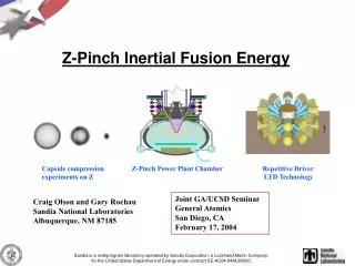
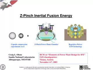
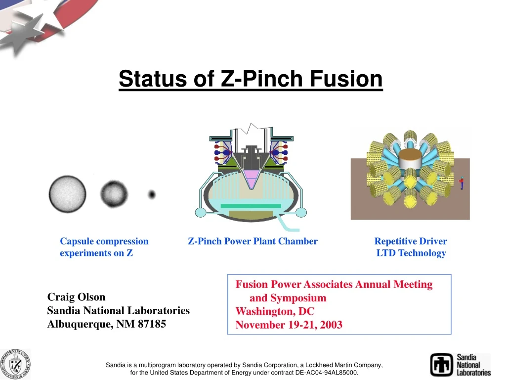
Status of Z-Pinch Fusion Capsule compression Z-Pinch Power Plant Chamber Repetitive Driver experiments on Z LTD Technology Fusion Power Associates Annual Meeting and Symposium Washington, DC November 19-21, 2003 Craig Olson Sandia National Laboratories Albuquerque, NM 87185 Sandia is a multiprogram laboratory operated by Sandia Corporation, a Lockheed Martin Company,for the United States Department of Energy under contract DE-AC04-94AL85000.
The long-range goal of Z-Pinch IFE is to produce an economically-attractive power plant using high-yield z-pinch-driven targets (3 GJ) at low rep-rate (0.1 Hz) Z-Pinch IFE DEMO (ZP-3, the first study) used 12 chambers, each with 3 GJ at 0.1 Hz, to produce 1000 MWe
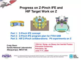
2038 2024 2018 2012 2008 2004 1999 Z-Pinch IFE Road Map Z-Pinch IFE DEMO Z-Pinch ETF (ETF Phase 2) $1B Laser indirect-drive Ignition Z-Pinch High Yield Z-Pinch Ignition High Yield Facility (ETF Phase 1) Z-Pinch IRE $150M (TPC) +op/year Z-Pinch IFE target design $5M /year Z-Pinch IFE target fab., power plant technologies $5M /year FI ZR Z Z-Pinch IFE PoP $10M /year Z-Pinch IFE target design $2M /year Z-Pinch IFE target fab., power plant technologies $2M /year Z-Pinch IFE CE $400k /year (SNL LDRD +) NIF Year Single-shot, NNSA/DP Repetitive for IFE, OFES/VOIFE
Driver pulsed power: _________ Marx generator/ magnetic switching linear transformer driver water line technology (RHEPP technology) (LTD technology) Power feed: ____ triax coax RTL: ____ Flibe/electrical coating Flibe immiscible material (e. g., low activation ferritic steel) Target: __ double-pinch dynamic hohlraumfast ignition Chamber: _ dry-wall wetted-wall thick-liquid wall solid/voids Z-Pinch IFE Matrix of Possibilities (choose one from each category) Z-Pinch Driver: ______________ Marx generator/ magnetic switching linear transformer driver water line technology (RHEPP technology) (LTD technology) RTL (Recyclable Transmission Line): _____ Flibe/electrical coating immiscible material (e. g., low activation ferritic steel) Target: _ double-pinch dynamic hohlraumfast ignition Chamber: ____ dry-wall wetted-wall thick-liquid wall solid/voids (e. g., Flibe foam)
Time (s) Pulsed-power provides compact, efficient time compression and power amplification x rays ~1.8 MJ Z vacuum Electrical to x-ray energy Conversion efficiency > 15% water Marx 11.4 MJ
Z-pinches offer the promise of a cost-effective energy-rich source of x-rays for IFE High Yield Facility ZR Z Saturn Proto II Supermite ZR will be within a factor of 2-3 in current (4-9 in energy) of a High Yield driver.
( 90 MA) ( 60 MA) (10 MA) (1 MA)
RTL (Recyclable Transmission Line)
Z-pinch power plant chamber uses an RTL (Recyclable Transmission Line) to provide the standoff between the driver and the target INSULATOR STACK (connects to driver) RTL FLIBE JETS Z-PINCH TARGET 10-20 Torr Inert Gas Yield and Rep-Rate: few GJ every 3-10 seconds per chamber (0.1 Hz - 0.3 Hz) Thick liquid wall chamber: only one opening (at top) for driver; nominal pressure (10-20 Torr) RTL entrance hole is only 1% of the chamber surface area (for R = 5 m, r = 1 m) Flibe absorbs neutron energy, breeds tritium, shields structural wall from neutrons Eliminates problems of final optic, pointing and tracking N beams, high speed target injection Requires development of RTL
RTL replacement requires only modest acceleration for IFE L = 0.5 a t2 , or a ~ 1/t2 Acceleration is 104 less than for IFE target injection for ions or lasers 104 g 1 g 10 g 0.1 g 100 g 1,000 g rifle bullet 0.01 g IFE RTL replacement for rep-rated z pinches Prometheus-L OSIRIS, SOMBRERO, Prometheus-H Car (0 - 60 mph in 10 s) IFE target injection for ions and lasers (~ 10 Hz) (~ 0.1 Hz)
Status of RTL Research RTL electrical turn-on Saturn experiments at 10 MA (2000) tin, Al, stainless-steel all show negligible losses RTL low-mass and Saturn experiments at 10 MA (2001) electrical conductivity 20 mylar; 50, 100, 250 steel RTL mass could be as low as 2 kg RTL mass 50 kg has low resistive losses RTL structural Calculations (U. Wisconsin) (2002) full-scale RTL (50 kg) of 25 mill steel ok for 10-20 Torr RTL manufacturing Allowed RTL budget is a few $ for 3 GJ Flibe casting ($0.70/RTL) ferritic steel stamping ( $1.20-3.95/RTL) Current RTL research structural integrity shrapnel formation RTL manufacturing/cost vacuum connections activation/waste stream analysis shock disruption to fluid walls foam Flibe
RTL Structural RTL FINITE ELEMENT MODEL constructed in ANSYS to perform structural analysis R = 50 cm r = 5 cm L = 200 cm 25 mil steel disc 10 cm lip Fusion Technology Institute University of Wisconsin, Madison
RTL Structural PRELIMINARY BUCKLING ANALYSIS of steel RTL 78 Torr RTL buckles at 1.52 psi = 78 Torr as shown 20 Torr no effect (safe operating point) Fusion Technology Institute University of Wisconsin, Madison
Laser Source Cones 5.5 mm 10 mm NIF Scale Z-pinch-driven-hohlraums have similar topology to laser-driven-hohlraums, but larger scale-size Double ended hohlraum 35 mm Dynamic hohlraum 6 mm
solid Be solid DT DT gas (0.3 mg/cm3) 0.218 cm radius 0.240 cm radius 0.259 cm radius The baseline DEH capsule yields 380 MJ withan ignition margin similar to a NIF capsule Capsule Performance Parameters Peak drive temperature In-flight aspect ratio Implosion velocity Convergence ratio Total RT growth factor Peak density Total rr Driver energy Absorbed energy Yield Burnup fraction 223 eV 37 2.9 x 107 cm/s 36 420 750 g/cm3 3.15 g/cm2 16 MJ 1.12 MJ 380 MJ 31% J.H. Hammer, et al., Phys Plasmas6, 2129
Summary – Double-ended hohlraum ICF status • Simulation codes and analytic modeling have been validated by measurements of time-dependent z-pinch x-ray production, z-pinch hohlraum temperatures, and capsule hohlraum temperatures • A reproducible, single power feed, double z-pinch radiation source with excellent power balance has been developed for ICF capsule implosion studies • The Z-Beamlet Laser (ZBL) is routinely used as an x-ray backlighter at x-ray energies up to 6.75 keV • Achieved capsule convergence ratios of 14-20 • Capsule symmetry (P2 and P4) in double-pinch hohlraums on Z can be systematically controlled with demonstrated time-integrated symmetry of ≤ 3% • Optimum hohlraums on Z should produce time-integrated radiation symmetry of ≤ 1% for 5 mm diameter capsules and absorbed energies of 25 kJ • P4 shimming shots are scheduled in collaboration with LLNL and LBL HIF program
10.0 8.0 Radius (mm) 6.0 4.0 2.0 0.0 1.2 0.4 0.6 0.8 1 Double-Ended Hohlraum Concept Publications Concept Hammer, Tabak, Wilks, et. al., Phys. Plasmas, 6, 2129(1999) Hohlraum energetics Cuneo, Vesey, Porter et al., Phys. Plas. 8, 2257 (2001) Cuneo, Vesey, Hammer et al., Laser Particle Beams, 19, 481 (2001) Foam ball radiation symmetry Hanson, Vesey, Cuneo et al., Phys. Plas. 9, 2173 (2002) Double pinch performance Cuneo, Vesey, Porter et al., Phys. Rev. Lett. 88, 215004 (2002) Symmetric capsule implosions Bennett, Cuneo, Vesey et al., Phys. Rev. Lett. 89, 245002 (2002) Bennett, Vesey, Cuneo et al., Phys. Plasmas, 10, 3717 (2003) Symmetry control Vesey, Cuneo, Bennett et al., Phys. Rev. Lett. 90, 035005 (2003) Vesey, Bennett, Cuneo et al., Phys. Plasmas 10, 1854 (2003) Diagnostics Sinars, Cuneo, Bennett et al., Rev. Sci. Instrum., 74, 2202 (2003) Sinars, Bennett, Wenger, et al., Appl. Opt., 19, 4059, (2003) Stygar, Ives, Fehl, Cuneo et al., accepted for publication in Phys. Rev. E Cuneo, Chandler, Lebedev et al., in preparation for Phys. Plasmas Waisman, Cuneo, Stygar et al., in preparation for Phys. Plasmas Pinch physics
The initial dynamic hohlraum high yield integrated target design produces a 527 MJ yield at 54 MA Capsule Performance Parameters solid Be Peak drive temperature In-flight aspect ratio Implosion velocity Convergence ratio DT KE @ ignition Peak density Total rr Driver energy Absorbed energy Yield Burnup fraction 350 eV 48 3.3 x 107 cm/s 27 50% 444 g/cm3 2.14 g/cm2 12 MJ 2.3 MJ 527 MJ 34% Be+3% Cu solid DT DT gas (0.5 mg/cm3) 0.225 cm radius 0.249 cm radius 0.253 cm radius 0.275 cm radius J.S. Lash et al., Inertial Fusion Sciences & Apps 99, p583
Summary – Dynamic Hohlraum ICF status • The primary radiation source is a thin radiating shock in the foam converter • Shock timing and capsule implosions in good agreement with rad-MHD modeling • Demonstrated >200 eV x-ray drive temperatures in dynamic hohlraums on Z • Imploded thin shell surrogate capsules absorbing 20-40 kJ of thermal x-rays (NIF-sized capsules) • Measured Te~1 keV, ne~1x10²³ from Ar K-shell spectra from imploded capsules • Measured 2.6±1.3x10¹⁰ thermonuclear D-D neutrons from ICF capsules absorbing >20 kJ • Symmetry measurements of capsule core x-rays made through ‘thin walled’ dynamic hohlraums (a/b~0.6, CR~6) • Capsule x-ray emission history (PCDs) in good agreement with simulations • Capsule implosion time reproducible to 160 ps
Dynamic Hohlraum Concept Publications • Concept • V.P Smirnoff, et al., Plasma Phys. Controlled Fusion 33, 1697, (1991) • M. K. Matzen, Phys. Plasmas 4, 1519 (1997) • J.H. Brownell, et al., Phys Plasmas5, 2071, (1998) • D.L. Peterson, et al., Phys Plasma 6 (1999) • J.S. Lash, et al., Proceedings of Inertial Fusion Sci. App. 1999, (Elsevier, Paris 2000), Vol. I, p 583 • Energetics • T. W. L. Sanford, et al., Phys. Rev. Lett., 5511 (1999) • T.J. Nash, et al, Phys Plasmas 6, 2023 (1999) • R.J. Leeper, et al., Nucl. Fusion 39, 1283 (1999) • J.J. MacFarlane, et al., Rev. Sci. Instrum. 70, No. 1, p.1, (1999) • S. A. Slutz, et al., Phys. Plasmas 8, 1673 (2001) • T. W. L. Sanford, et al., Phys. Plasmas 9, No. 8, p. 3573 (2002) • T.J. Nash, et al., , Rev. Sci. Instrum. 74, 2211 (2003) • ICF capsule implosions and neutron production • S. A. Slutz, et al., Phys Plasmas 10, No. 5, p. 1875 (2003) • J.E. Bailey, et al., Physical Review Letters 89, No. 095004 (2002) 56 • J.E. Bailey, et al., – LANL preprint server, physics/0306039 • ICF ignition scaling • T.A. Mehlhorn, et al., Plasma Phys Controlled Fusion – to be published, 2003
Code calculations and analytic scaling predict z-pinch driver requirements for IFE DEMO Double-Pinch Hohlraum Dynamic Hohlraum current /x-rays Eabs / yield current /x-rays Eabs / yield 54 – 95 MA 12-37 MJ 2.4 – 7.2 MJ 530 – 4400 MJ 2 x 62-68 MA 2 x (16-19) MJ 1.3 – 2.6 MJ 400 – 4000 MJ Based on these results, an IFE target for DEMO will require: double-pinch hohlraumdynamic hohlraum 36 MJ of x-rays (2x66MA) 30 MJ of x-rays (86 MA) 3000 MJ yield 3000 MJ yield (G = 83) (G = 100) J. Hammer, M. Tabak, R. Vesey, S. Slutz, J. De Groot
Thick liquid walls essentially alleviate the “first wall” problem, and can lead to a faster development path
Z-IFE DEMO produces 1000 MWe DEMO parameters: yield/pulse: 3 GJ driver x-rays/pulse (86 MA) 30 MJ energy recovery factor: 80% thermal recovery/pulse: 2.4 GJ time between pulses/chamber: 3 seconds thermal power/unit 0.8 GWt thermal conversion efficiency 45 % electrical output/unit 0.36 GWe number of units 3 total plant power output 1.0 GWe Major cost elements: LTD z-pinch drivers (3) $900 M RTL factory $500 M Target factory $350 M Balance of Plant $900 M Total Cost $2.65 G ZP-3 (the first study) used 12 chambers, each with 3 GJ at 0.1 Hz Z-Pinch power plant studies: G. Rochau, et al. : ZP-3 J. De Groot, et al.: Z-Pinch Fast Ignition Power Plant
Z-IFE PoP is a set of four experiments (shown here) plus IFE target studies plus IFE Power Plant studies RTL experiments issues: shape, inductance, mass, electrical/structural, manufacture, cost power flow: limits, optimal configuration, convolute location chamber/interface issues: vacuum/electrical, debris removal, shielding RTL experiment test on Z Repetitive driver- LTD (Linear Transformer Driver) experiment 1 MA, 1 MV, 100 ns, 0.1 Hz driver design/construction/testing LTD is very compact (pioneered in Tomsk, Russia) no oil, no water LTD technology is modular, scalable, easily rep-ratable 1 MA, 100 kV cell is being developed this year (SNL/Tomsk) Shock mitigation scaled experiments 3 GJ yield is larger than conventional IFE yields of 0.4-0.7 GJ coolant streams, or solids/voids, may be placed as close to target as desired shock experiments with explosives and water hydraulic flows validate code capabilities for modeling full driver scale yields Full RTL cycle @ 0.1 Hz experiment integrated experiment (LTD, RTLs, z-pinch loads, 0.1 Hz) demonstrate RTL/z-pinch insertion, vacuum/electrical connections, firing of z-pinch, removal of remnant, repeat of cycle z-pinches have 5 kJ x-ray output per shot Cost: $14M/year for 3-5 years, $5M for FY04 to start $4M for Z-Pinch IFE for FY04 is in House-Senate Conference Agreement
High current pulsed power accelerators drive many different load configurations High Current Z-pinch x-ray source Magnetic pressure High Z Low to mid Z • Isentropic Compression Experiments (ICE) • Flyer Plates • Basic science Hohlraum source (Planckian) K-shell source (Non-Planckian) • ICF -Ignition & high yield - Inertial Fusion Energy • Weapon physics • Shock physics • Basic science • Radiation effects • Weapon effects • IFE chamber materials • Basic science IFE ICF/WP RES ICE/Flyer Plates High Current Laser